

A power module for DC electromagnetic arrester
A technology of electromagnetic brake and power module, which is applied to the parts of the brake, the type of the brake, the electromagnet, etc., can solve the problems of waste of electric energy and raw materials, faults, and easy occurrence of motors, etc., and achieve low heat generation, enhanced versatility, and coil absorption reliable effect
- Summary
- Abstract
- Description
- Claims
- Application Information
AI Technical Summary
Problems solved by technology
Method used
Image

Examples
Embodiment Construction
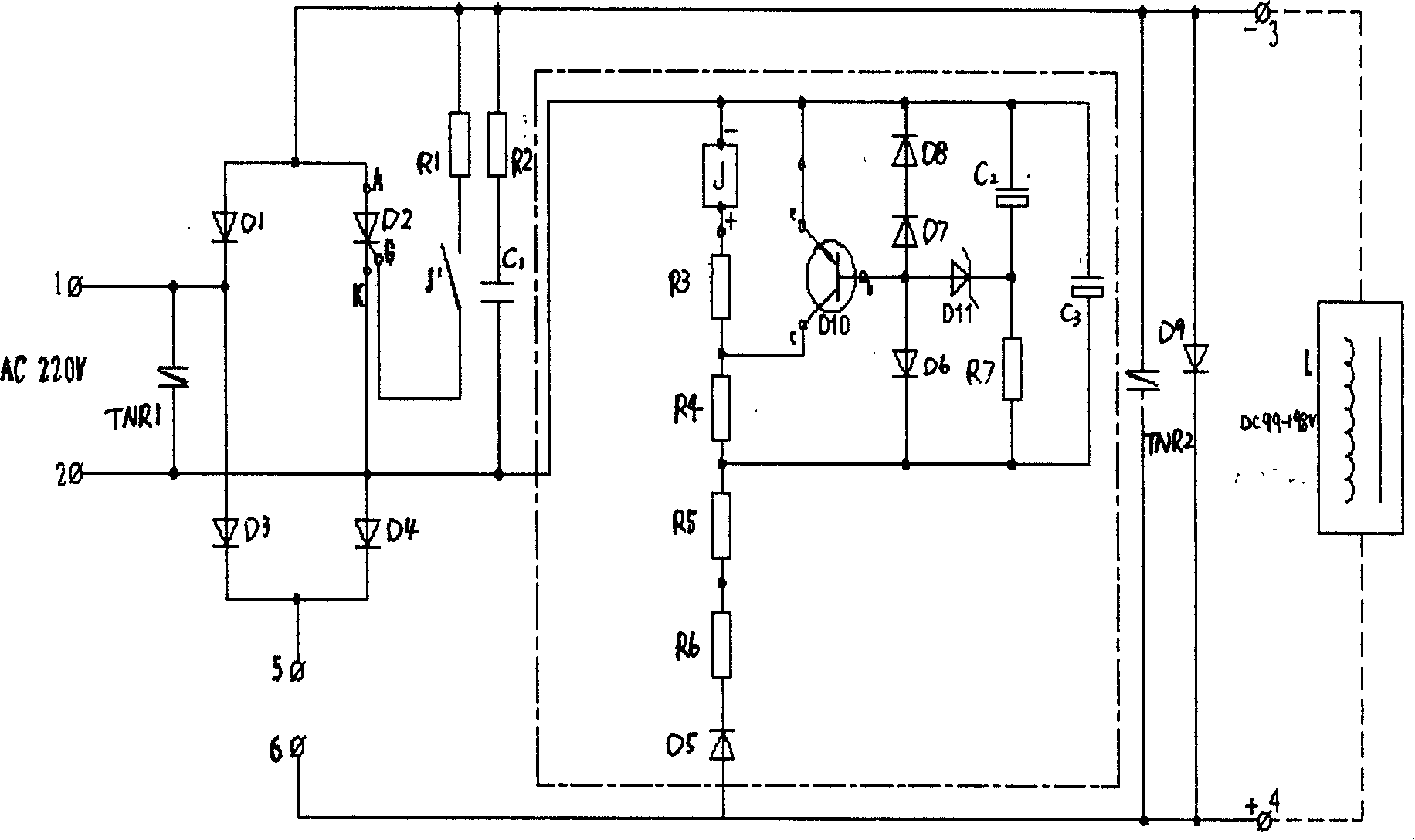
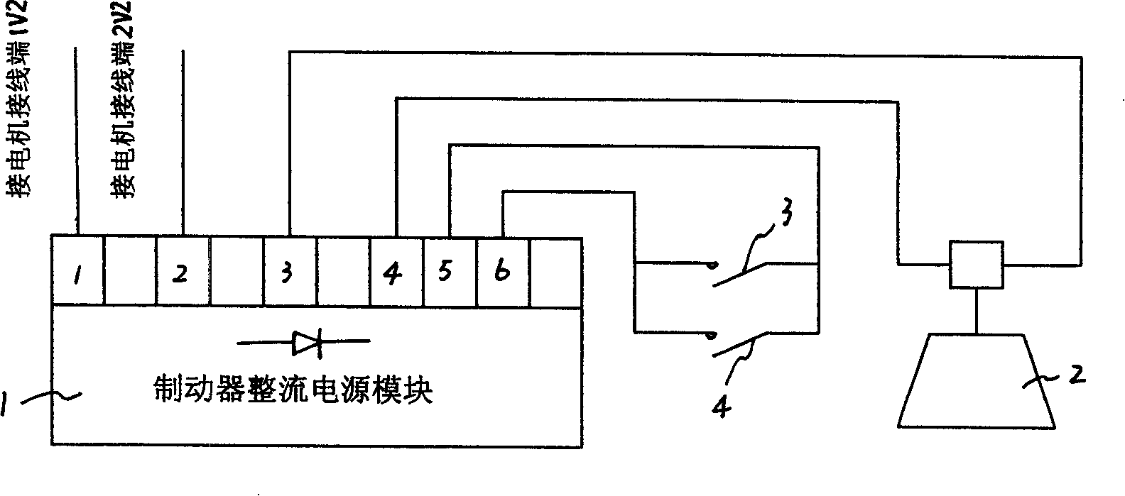
[0008] refer to figure 1 , the power supply module of the DC electromagnetic brake, including the main circuit and the control circuit. The control circuit is inside the dot-dash line frame, and the main circuit is outside the dot-dash line frame. Connect to a bridge rectifier circuit composed of 4 diodes D1, D2, D3, D4, among which D2 is a thyristor, and the working power of the motor: 380VAC 50Hz or 220VAC 50Hz. The power frequency alternating current of the working power supply of the motor is directly rectified into a direct current power supply for the electromagnetic coil. The negative output terminal of the diode bridge rectifier circuit is connected to the negative pole of the DC output, the positive output terminal of the bridge rectifier circuit is connected to two connection terminals 5 and 6 and then connected to the positive pole of the DC output, and a varistor TNR2 and a diode D9 are connected in parallel at the DC output terminal , The electromagnetic coil is ...
PUM
 Abstract
Description
Claims
Application Information