
Electric heating method for reduction pot and reduction pot used for the same

A reduction tank and electric heating technology, applied in the direction of furnace heating elements, etc., can solve the problems of large heat radiation and other heat losses, difficult to reduce production costs, and long heating time, so as to reduce heat energy loss, simplify production costs, Fast heating effect

Inactive Publication Date: 2012-07-18
GUIZHOU SHIJI TIANYUAN MINING IND
View PDF0 Cites 0 Cited by
  • Summary
  • Abstract
  • Description
  • Claims
  • Application Information

AI Technical Summary

Problems solved by technology

Therefore, the heating time is too long and the waste of heat energy is caused, and the time required for the complete reaction of the reducing material in the reduction tank is also long. The time required for the existing reduction tank from feeding to the completion of the reduction reaction is generally within 8 to 12 hours. between
This heating method has low thermal conductivity, slow temperature rise, low production efficiency per unit time, large heat radiation and other heat losses, large energy consumption, and it is difficult to reduce production costs. The environment also pollutes

Method used


Image

  • Electric heating method for reduction pot and reduction pot used for the same
  • Electric heating method for reduction pot and reduction pot used for the same
  • Electric heating method for reduction pot and reduction pot used for the same

Examples


Embodiment

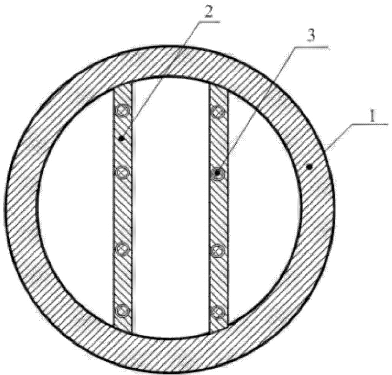
[0025] Embodiment: the electric heating method of reduction tank, as figure 1 As shown, a heat conductor 2 is arranged in the tank body of the reduction tank 1, and an electric heating rod 3 is embedded in the heat conductor. heating.

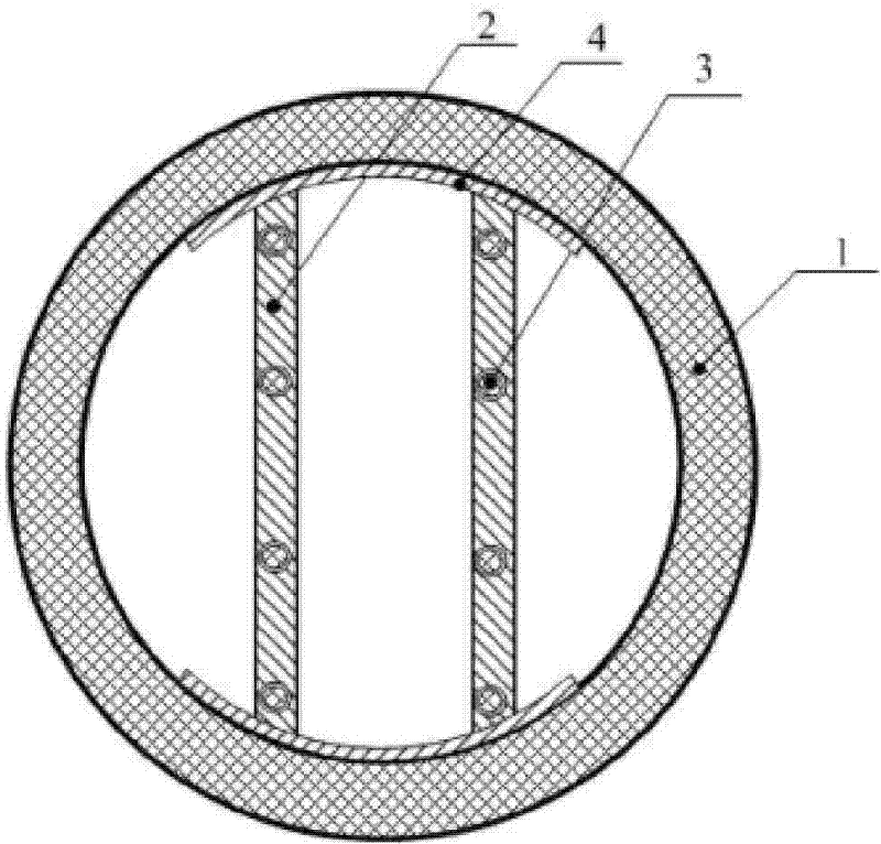
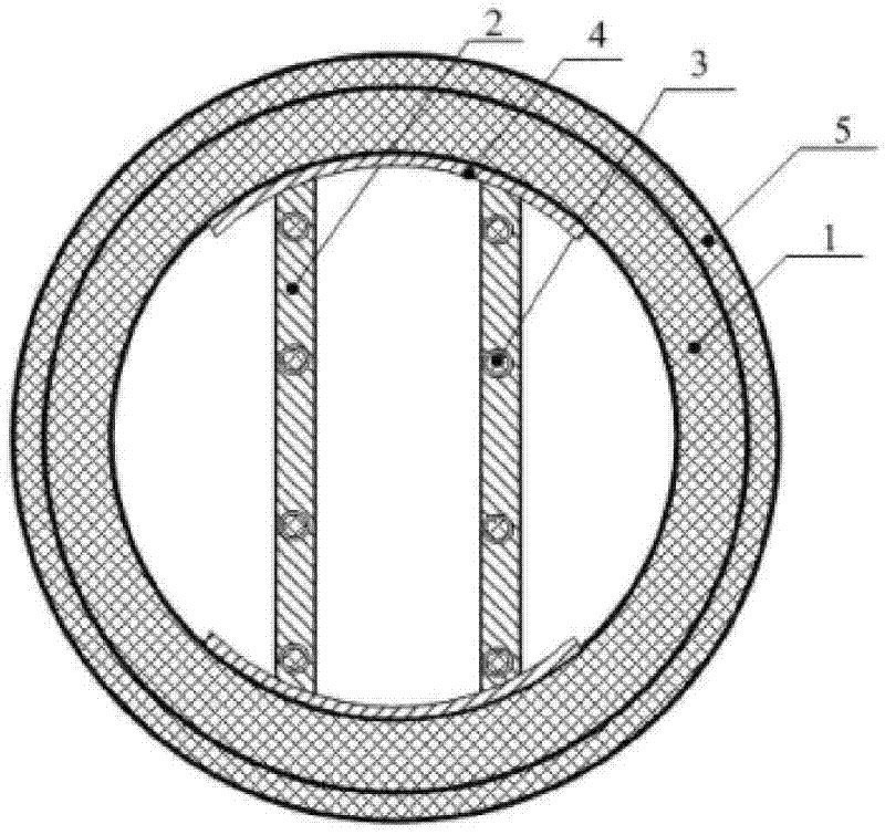
[0026] The reduction tank used in the above-mentioned reduction tank electric heating method, such as Figure 1 to Figure 9 As shown, the reduction tank 1 is a cylindrical, rectangular or arbitrary cylindrical structure. One end of the reduction tank 1 is provided with a charging port, and the other end is closed or provided with a slag discharge port; It is an integrated structure connected with the inner wall of the reduction tank, or the heat conductor is a movable structure tightly nested in the reduction tank; the shape and setting method of the heat conductor 2 are arbitrary, and the heat conductor 2 is embedded with an electric heating rod 3. The connecting terminal on the bar is connected with a lead, and the lead passes through the l...


PUM


Abstract

The invention discloses an electric heating method for a reducing pot and the reducing pot used by the method, wherein, a heat conductor is arranged inside a pot body of the reducing pot; an electrical bar is embedded into the heat conductor; heat generated after the electrical bar is electrified is conducted through the heat conductor, and reducing materials in the reducing pot are heated. The reducing pot (1) takes the structure of a cylinder, wherein, a charging hole is arranged on one end of the reducing pot; the other end of the reducing pot is closed or provided with a slag notch; the heat conductor (2) is arranged inside the reducing pot (1); the heat conductor (2) and the inner wall of the reducing pot (1) are integrated into a whole or the heat conductor (2) is a movable structure which is closely embedded and sleeved into the reducing pot (1); shape and set mode of the heat conductor (2) are random; the electrical bar (3) is embedded into the heat conductor (2). The invention can be used for auxiliary heating of the prior heating method and also can be completely used for electric heating, and has the advantages of great reduction of reaction time of reducing materials, improvement of production rate per unit time, reduction of production cost and capability of reducing environmental pollution.

Description

technical field [0001] The invention relates to a heating method for metal vacuum smelting and a reduction tank used, belonging to the field of metal vacuum smelting heating. Background technique [0002] In the production of metal vacuum smelting by thermal reduction method, the reduced material produced through the batching and pressing process is sent to the reduction tank for reduction reaction. According to the different reducing agents, the reduction reaction temperature is generally required to be 1000-1300 °C, and the internal pressure of the reduction tank is less than 10Pa. ~13 Pa. The current heating method for the reduction tank is: place the reduction tank in the reduction furnace, use the heat energy generated by the combustion of coal gas or coal-water slurry to heat the reduction tank, so that the reduction tank placed in the reduction furnace is heated up, and the reduction tank transfers the heat energy again Give the reducing material in the reduction tan...

Claims


Application Information

Patent Timeline
Patent Type & Authority Patents(China)
IPC IPC(8): C22B5/00H05B3/64
Inventor 张继强黄贵明
Owner GUIZHOU SHIJI TIANYUAN MINING IND
Learn More