Drying process and equipment for powdered urea formaldehyde condensate

A technology of powder urea-formaldehyde resin and drying process, which is applied in the direction of drying solid materials, lighting and heating equipment, heating to dry solid materials, etc., can solve problems such as sticking to the wall, reduce sticking to the wall, reduce the phenomenon of sticking to the wall, and reduce adhesion Effect

Inactive Publication Date: 2008-06-11
PETROCHINA CO LTD
View PDF0 Cites 7 Cited by
  • Summary
  • Abstract
  • Description
  • Claims
  • Application Information

AI Technical Summary

Problems solved by technology

[0004] The purpose of the present invention is to overcome the defects of the prior art, reduce the energy loss during driving, recycle and utilize the energy in the production process step by step, solve the phenomenon of powder urea-formaldehyde resin sticking to the wall, and improve the product quality of powder urea-formaldehyde resin

Method used


Image

  • Drying process and equipment for powdered urea formaldehyde condensate
  • Drying process and equipment for powdered urea formaldehyde condensate
  • Drying process and equipment for powdered urea formaldehyde condensate

Examples


Embodiment 1

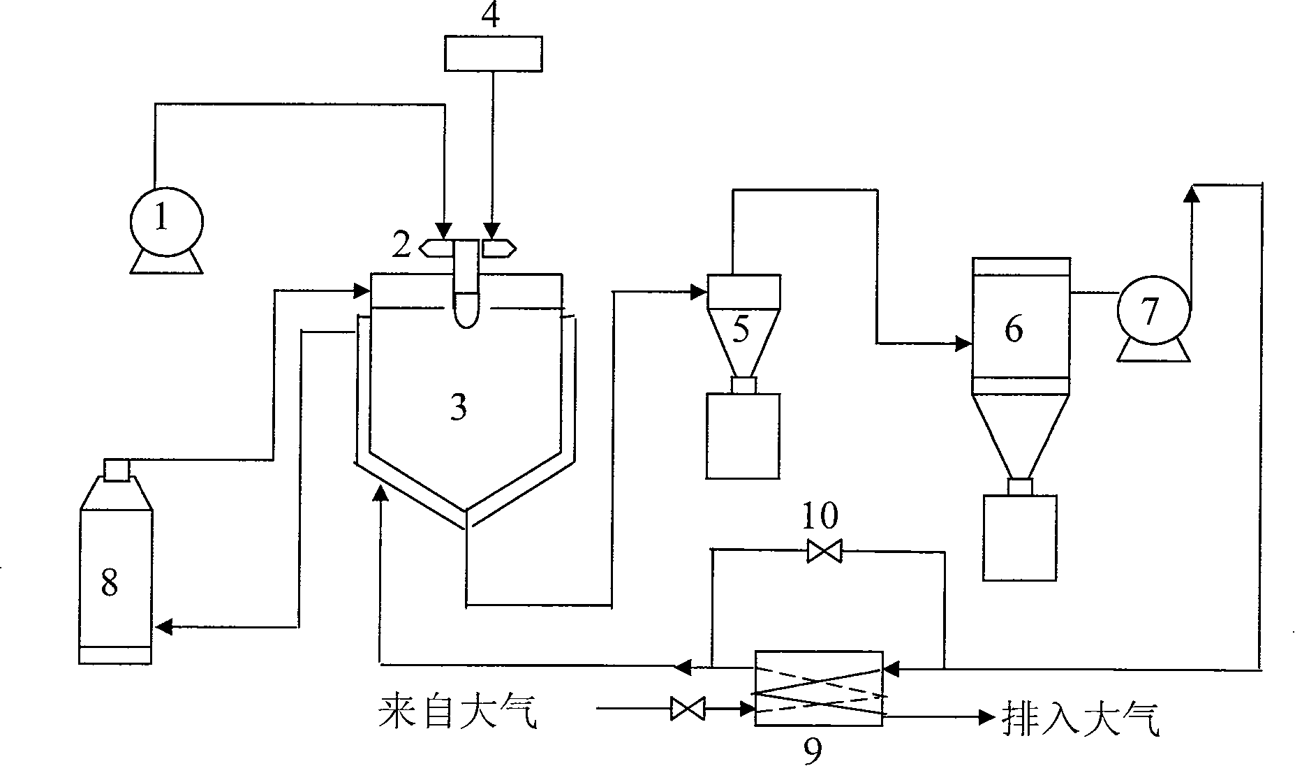
[0026] use figure 2 The powder urea-formaldehyde resin drying process shown is specifically: open the induced draft fan 7 and the air heater 8, the hot air passes through the drier, the cyclone separator 5, and the bag filter 6, and enters the primary air preheating side from the induced draft fan outlet Directly enter the interlayer air duct of the dryer, and enter the air heater after the second preheating. After 8 minutes, the temperature of the hot air reaches the process requirement of 155°C. Close the primary air preheating gas bypass, and adjust the peristaltic pump to add 1000ml of urea-formaldehyde resin emulsion to the second flow Type atomizing nozzle, the solid content of the urea-formaldehyde resin emulsion is 48%. Spray under the action of compressed air to form urea-formaldehyde resin mist droplets. After the mist droplets are dried by hot air in the drier, they enter the storage tank at the bottom of the cyclone separator and are dried continuously for 32 minu...

Embodiment 2

[0027] Example 2: Using figure 2The powder urea-formaldehyde resin drying process shown is specifically: open the induced draft fan 7 and the air heater 8, the hot air passes through the drier, the cyclone separator 5, and the bag filter 6, and enters the primary air preheating side from the induced draft fan outlet Directly enter the interlayer air duct of the dryer, and enter the air heater after the second preheating. After 5 minutes, the temperature of the hot air reaches the process requirement of 145°C. Close the primary air preheating gas bypass, and adjust the peristaltic pump to add 1000ml of urea-formaldehyde resin emulsion to the second flow. Type atomizing nozzle, the solid content of the urea-formaldehyde resin emulsion is 48%. Spray under the action of compressed air to form urea-formaldehyde resin mist droplets. After the mist droplets are dried by hot air in the dryer, they enter the storage tank at the bottom of the cyclone separator and dry continuously for ...


PUM


Abstract

The invention relates to drying process and equipment of powder urea resin, which mainly pumps urea-formaldehyde resin emulsion into an atomizer (2) by a pump (1). The urea-formaldehyde resin emulsion is sprayed into droplet by compressed air in a nozzle of a sprayer and enters a dryer (3) together with the compressed air. After being dried, the powder urea resin enters a cyclone separator (5) and waste gas is exhausted by an induced draft fan after filtered by a bag filter (6). The invention is characterized in that: the dryer (3) is provided with interlayer on the external wall; the waste gas hot air exhausted from the exit of the induced draft fan (7) is led into a primary air preheater (9) provided with an input port for cold air; the cold air enters the interlayer of the dryer after preheated and ascends along the dryer interlayer duct in a spiral; the air exhausted from the dryer interlayer is led into an air heater (8). The adoption of the drying process and equipment of powder urea resin can effectively recover energy by grades and has the characteristics of saving energy and reducing sticking on the wall.

Description

technical field [0001] The invention relates to the production field of powder urea-formaldehyde resin, in particular to a powder urea-formaldehyde resin drying process and equipment using a spray drying method. Background technique [0002] In the powder urea-formaldehyde resin spray production process, the traditional production method is to pump the urea-formaldehyde condensate into the atomizer, and spray the liquid urea-formaldehyde resin into a fine mist through compressed air, and at the same time conduct mass transfer and heat transfer to make the moisture Vaporization, the material is dried and enters the cyclone separator together with the moisture, and the solid powder urea-formaldehyde resin is obtained at the lower port of the cyclone separator. The production process schematic diagram is as follows figure 1 As shown, the urea-formaldehyde resin emulsion is pumped to the atomizer 2 through the pump 1. The sprayer is a two-flow atomizing nozzle. The urea-formalde...

Claims


Application Information

Patent Timeline
Patent Type & Authority Applications(China)
IPC IPC(8): F26B3/12F26B17/10
CPCY02P70/10
Inventor 齐国庆刘发强刘光利刘军韩燕王卫东安守义
Owner PETROCHINA CO LTD
Why Eureka
Try Eureka