Electrical control system of crankshaft rotor-bearing system dynamics experimental bench

A system dynamics, test-bed technology, applied in mechanical bearing testing, vibration testing, engine testing, etc., can solve the problems that restrict the development of the shipbuilding industry and the backward manufacturing capacity of marine crankshafts.

Active Publication Date: 2008-06-11
SHANGHAI ELECTRICGROUP CORP +2
View PDF0 Cites 15 Cited by
  • Summary
  • Abstract
  • Description
  • Claims
  • Application Information

AI Technical Summary

Problems solved by technology

However, in the prior art, there is no test bench similar to the vibration law and dynamics of the crankshaft, so people's understanding of the crankshaft rotor-bearing system is inhibited, and the manufacturing capacity of my country's marine crankshafts has been in a backward state, which seriously restricts Development of my country's Shipbuilding Industry

Method used


Image

  • Electrical control system of crankshaft rotor-bearing system dynamics experimental bench

Examples


Embodiment Construction

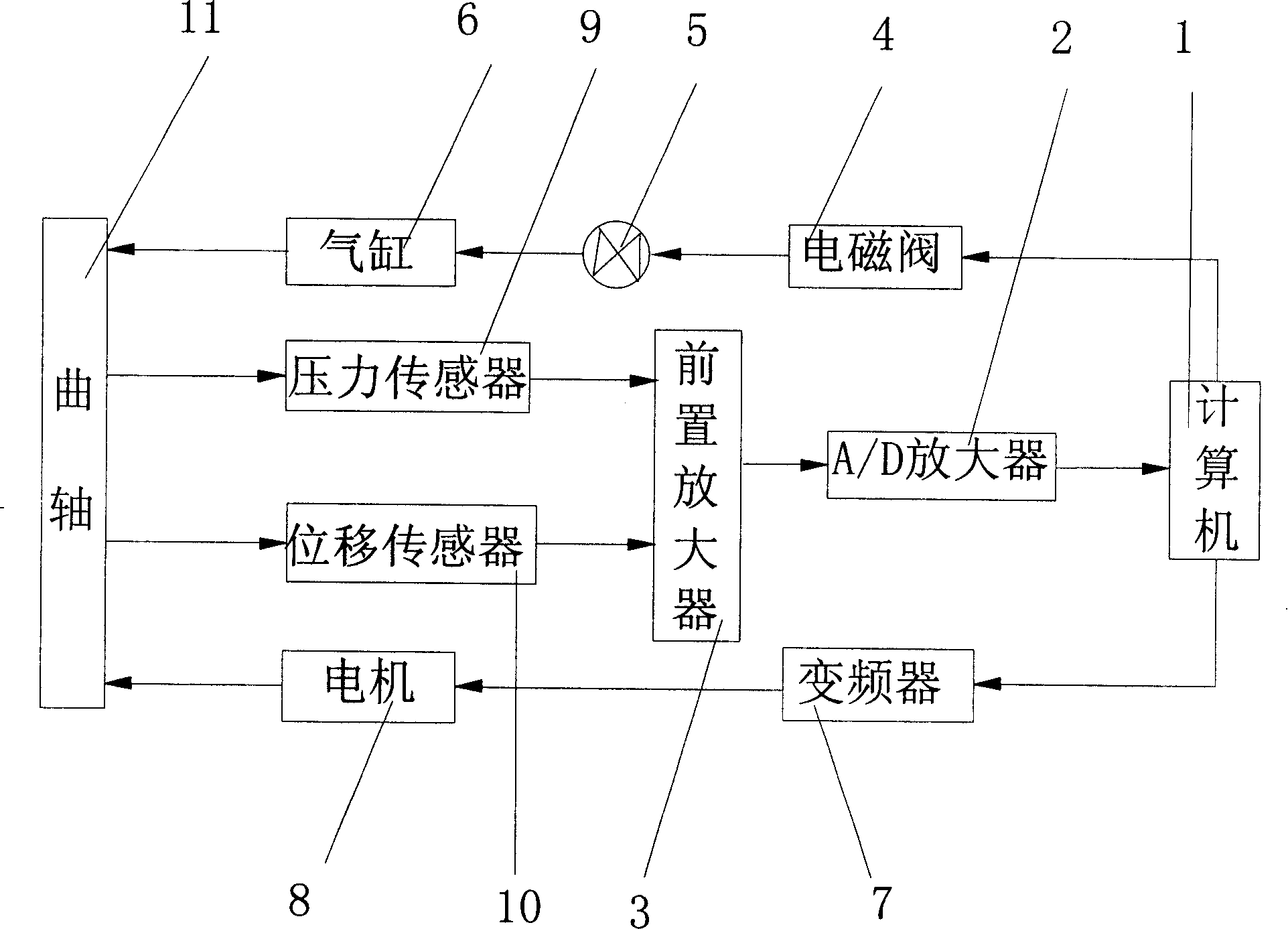
[0011] see figure 1 , the electrical control system of the crankshaft rotor-bearing system dynamics test bench of the present invention includes a computer controller 1, a preamplifier 3, an A / D converter 2, a solenoid valve 4, a cylinder 6, a variable frequency drive controller 7, and a drive motor 8. Pressure sensor 9, displacement sensor 10 and crankshaft 11, wherein, computer controller 1 is used to control the power on and off of solenoid valve 4 and drive motor 8 operation or rotating speed and to the vibration signal from pressure sensor 9 and displacement sensor 10 and The pressure signal is analyzed and processed, and it outputs pulse signals to the solenoid valve 4 and the variable frequency drive controller 7 respectively; the solenoid valve 4 receives the signal from the computer controller 1, and when it is powered, it is connected and outputs a signal to the cylinder 6 to control it. On-off; the cylinder 6 is loaded on the crankshaft 11, and it receives the on-of...


PUM


Abstract

The invention discloses a bent axle rotor-bearing system dynamics experiment table electric control system, which comprises a computer controller, a preposing enlarger, an A/D converter, a magnet valve, an air cylinder, an inverter drive controller, a drive engine, a pressure sensor, a displacement sensor and a bent axle. The utility model adopts the technical scheme of bent axle rotor-bearing system dynamics test bed electric control system in the invention, which can stimulate various faults mechanism load situation, on-line test and maintaining during the working process of bent axle, etc. The invention can help people to have complete knowledge to the bent axle rotor-bearing system, which is helpful for building more accurate interdependence relationship among each design index of multiple diesel engines, and provides the theory guidance on improving the performance of diesel engine further.

Description

technical field [0001] The invention relates to an electric control system of a crankshaft rotor-bearing system dynamics test bench. Background technique [0002] The crankshaft is one of the most important components in engines such as diesel engines, internal combustion engines, and steam engines. The reciprocating motion of the piston is converted into the rotational motion of the crankshaft through the connecting rod. The power of the diesel engine, internal combustion engine, and steam engine is output through the crankshaft, and directly or indirectly drives the gas distribution system, fuel injection pump, oil pump, water pump and other components. With the development of modern power equipment in the direction of high power, high efficiency, high reliability, and low noise, the requirements for the dynamic performance of the crankshaft system are getting higher and higher. [0003] Since the crankshaft is a typical asymmetric structural part with the characteristics...

Claims


Application Information

Patent Timeline
Patent Type & Authority Applications(China)
IPC IPC(8): G01M13/00G01M13/04G01M15/00G01M15/06G01M15/12G01M19/00G01M7/02G01M99/00
Inventor 张青雷张锁怀林尧武
Owner SHANGHAI ELECTRICGROUP CORP
Why Eureka
Try Eureka