Optical coherence tomography method and equipment therefor

A technology of optical coherence tomography and imaging method, which is applied in the field of optical measurement and medical detection equipment, can solve the problems of slow moving speed of reference light mirror, difficulty in moving, building, affecting measurement speed, etc. Polarization-dependent effects and effects of improved measurement accuracy

Active Publication Date: 2008-06-18
北京高光科技有限公司
View PDF0 Cites 44 Cited by
  • Summary
  • Abstract
  • Description
  • Claims
  • Application Information

AI Technical Summary

Problems solved by technology

[0013] 1. The system uses a space optical device, which is difficult to move and build, has poor practicability, and is easily affected by exter

Method used


Image

  • Optical coherence tomography method and equipment therefor
  • Optical coherence tomography method and equipment therefor
  • Optical coherence tomography method and equipment therefor

Examples


Embodiment Construction

[0060] The optical coherence tomography method and its device proposed by the present invention are described in detail in conjunction with the accompanying drawings and embodiments as follows:

[0061] The present invention first proposes an optical coherence tomography method, which is characterized in that it comprises the following steps:

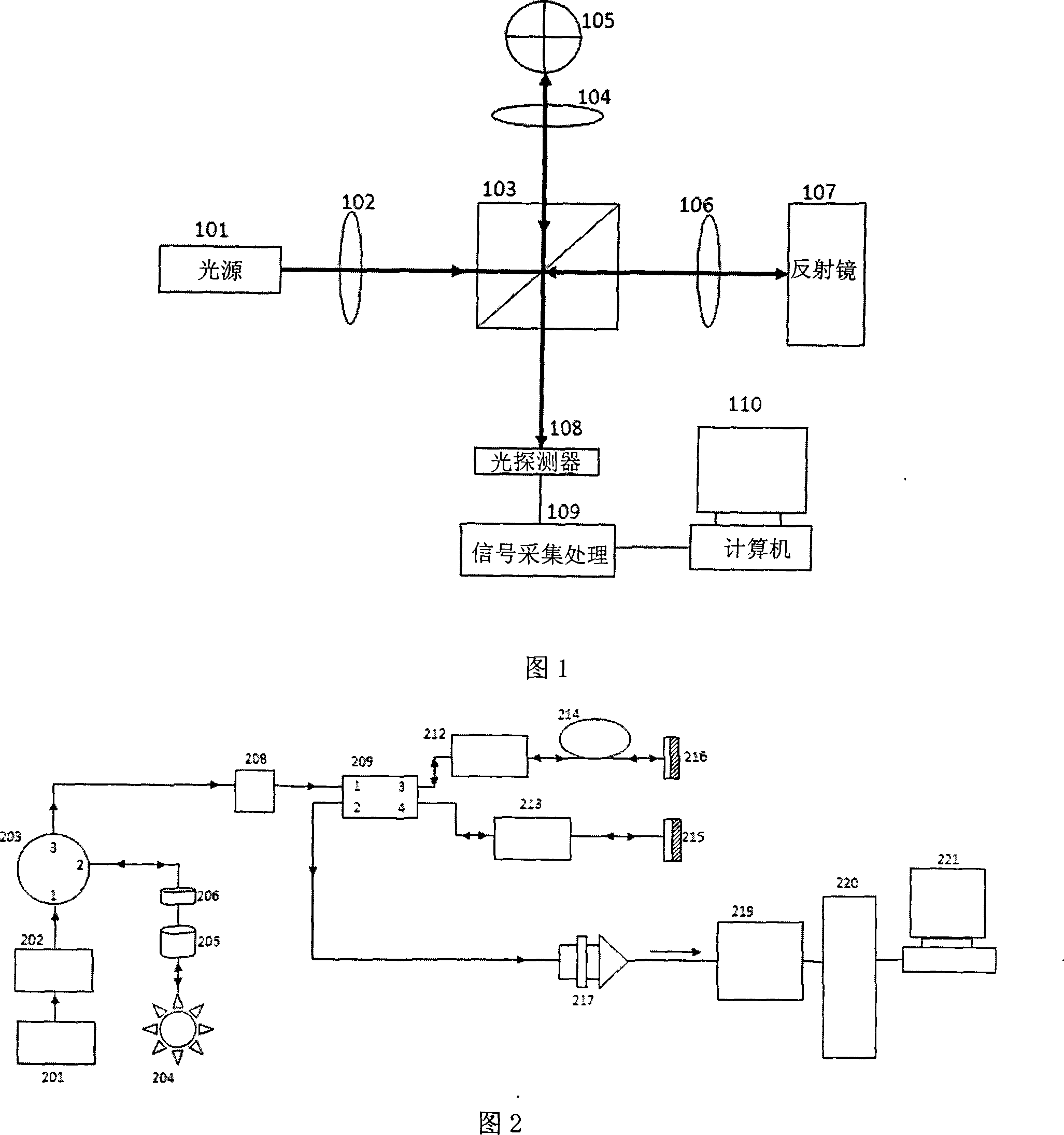
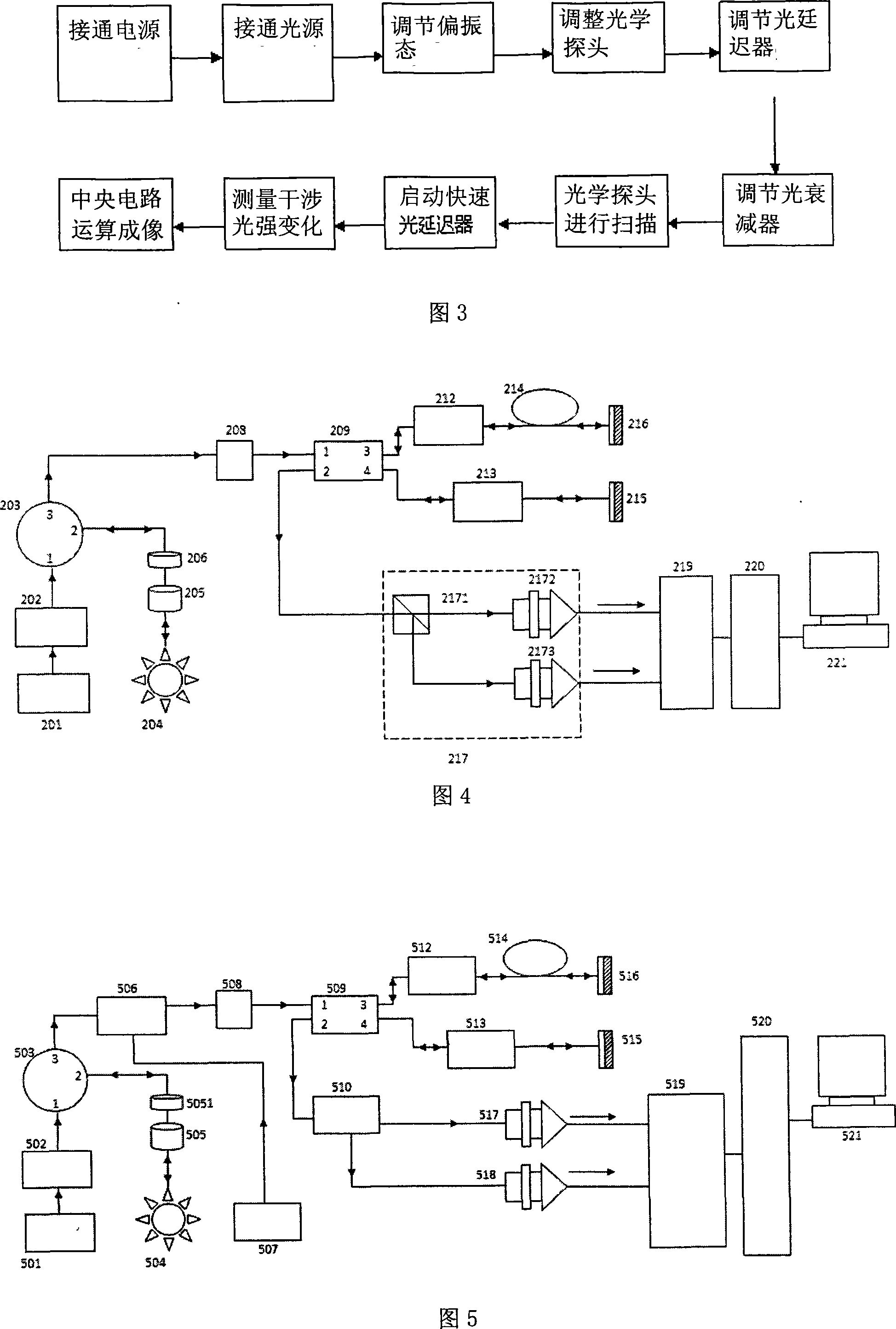
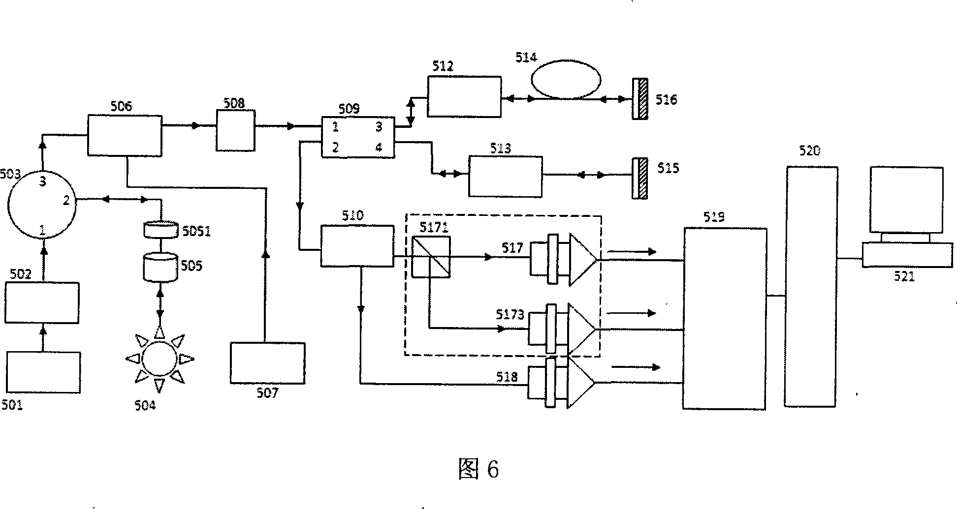
[0062] 1) The measurement light source emits a measurement beam, which passes through a light-transmitting device with a certain reflectivity (the reflectivity is between 4% and 10%) to generate a reflected light and a transmitted light, and the transmitted light is irradiated to the measured a point of an object;

[0063] 2) After the reflected light of the object under test returns from the original optical path, it is combined with the reflected light of the light-transmitting device into a beam of light for transmission, and then divided into two beams of light and enters the first optical path and the second optical path respective...


PUM


Abstract

The invention relates to optical coherent tomography method and the device, relating to the technical field of optical measurement and medical detecting instrument. The invention includes the following steps: (1) let the light beam to be measured generate reflected light and transmitted light which radiates to a detecting target object; the reflected light of the detecting target object returns from the original path and combines with the reflected light into one light beam which is then divided into two light beams; one of the light beam returns from the original path and the other is retained for a set light journey and then returns from the original path; the two returning light beams combine and generate interference and then enter a photodetector and generate relative electrical signals; (2) move the light beam irradiated to the detecting target object in all directions to scan the detecting target object; the adjustable light delaying element does one delaying operation each time the light beam is moved to a point; (3)repeat the operation to let the interferometric phase of the measured light correspond to different sections of the target object; (4)treat the interferometric photoelectric signals and send the treatment result to a computer for graphical analysis and display. The invention has the advantages that the device is convenient to move and small in size and the data is easy to process.

Description

technical field [0001] The invention belongs to the technical fields of optical measurement and medical detection instruments. In particular, it involves the use of coherent laser or light-emitting diode light sources to irradiate the measured object, and completes the three-dimensional imaging of the internal structure of the measured object through polarization state generation equipment, polarization state analysis equipment, optical phase fast adjustment equipment, and other optical path devices and photoelectric conversion analysis systems. and all fault data sets. Background technique [0002] Optical coherence tomography (OCT), abbreviated as OCT, has developed rapidly in the past ten years. New biotissue imaging techniques. It integrates semiconductor laser and ultra-fast laser technology, optical technology, ultra-sensitive detection technology, precision automatic control and computer image processing technology, and can perform non-destructive live detection on ...

Claims


Application Information

Patent Timeline
IPC IPC(8): A61B5/00G01N21/45
Inventor 姚晓天
Owner 北京高光科技有限公司
Why Eureka
Try Eureka