
Manipulator of automatic positioning and rapid grasping pipe piece

A self-positioning and fast technology, applied in the direction of manipulator, wellbore lining, tunnel lining, etc., can solve the problems such as limitation of segment posture adjustment, influence of tunnel forming quality, inflexible movement of rotating platform, etc., to achieve high segment assembly efficiency and improve Assembly efficiency and easy posture adjustment

Inactive Publication Date: 2008-06-18
SHENYANG HEAVY MACHINERY GROUP
View PDF0 Cites 23 Cited by
  • Summary
  • Abstract
  • Description
  • Claims
  • Application Information

AI Technical Summary

Problems solved by technology

Although the existing technology can meet the requirements of the rotation angle and position of the segments, the rotating platform connected with the segment can only realize two movements: the rotation around the tunnel radial horizontal force direction and the vertical force direction around the tunnel radial direction , the rest of the movement is realized by a large-stroke oil cylinder and a driving device. Obviously, the movement of the rotating platform is not flexible, that is, there are limitations in the attitude adjustment of the segment after the segment rotates to a predetermined angle. For the tunnel The molding quality will have a certain influence

Method used


Image

  • Manipulator of automatic positioning and rapid grasping pipe piece
  • Manipulator of automatic positioning and rapid grasping pipe piece
  • Manipulator of automatic positioning and rapid grasping pipe piece

Examples


Embodiment Construction

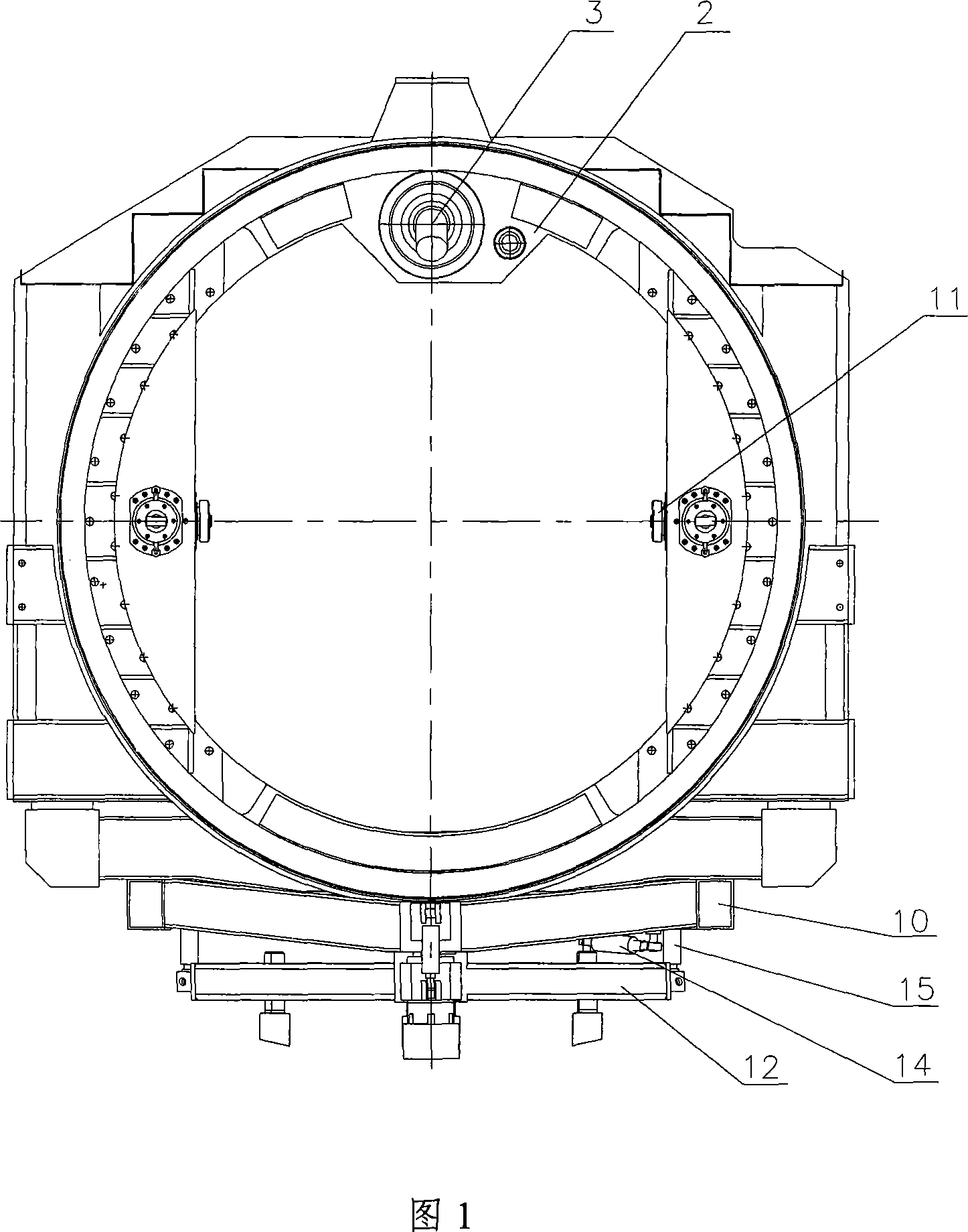
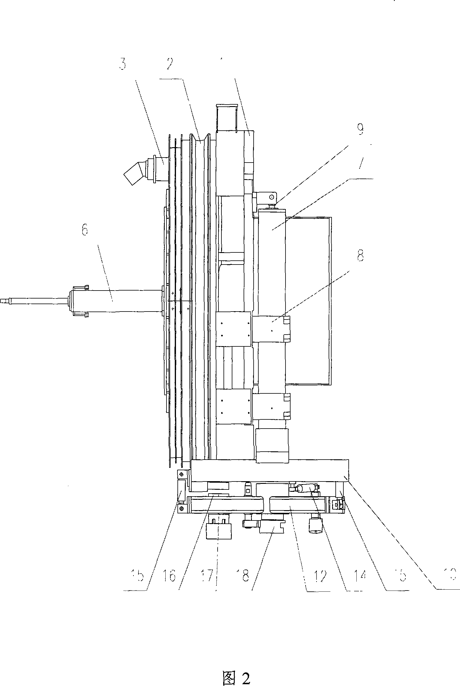
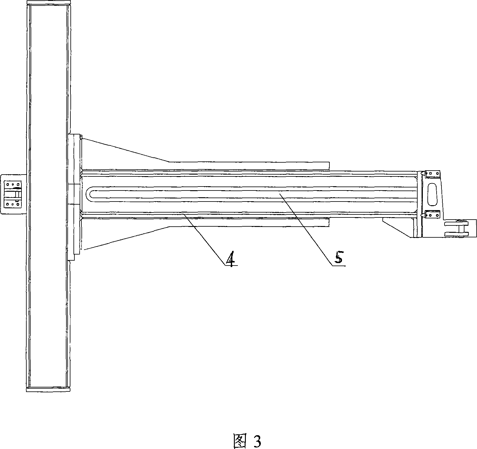
[0012] Referring to the accompanying drawings, the self-positioning and fast grabbing segment manipulator, the whole device consists of a rotating ring 1, a fixed ring 2, a driving device 3, a cantilever beam 4, a grooved track 5, two translation cylinders 6, two guide columns 7, and four guide sleeves 8. The second lifting cylinder 9, the lifting frame 10, the four rollers 11, the grasping platform 12, the grasping cylinder 13, the deflection cylinder 14, the three tilting cylinders 15, the positioning rod 16, the joint bearing 17, and the grasping head 18. The axial direction of the tunnel is set as the X axis, the tunnel radial horizontal direction is the Y axis, and the tunnel radial vertical direction is the Z axis; the axes of the rotating ring 1 and the fixed ring 2 coincide with the X axis, and the driving device 3 is fixed on the fixed ring 2. Its hydraulic motor drives the pinion through the reduction box, thereby driving the large ring gear and the rotating ring 1 co...


PUM


Abstract

Disclosed is a self-positioning manipulator for fast grasping segments used in tunnel engineering construction machine industry, which is composed of a rotating ring, a driving device, a cantilever beam, a lifting frame, four rolling wheels, a grasping platform, grasping oil cylinders and a grasping head. The axial direction of the tunnel is set as an X axis; the radial horizontal direction of the tunnel is set as a Y axis; the radial vertical direction of the tunnel is set as a Z axis. The axial lines of the rotating ring and a fixed ring coincide with the X axis; the driving device is fixed on the fixed ring; a hydraulic motor of the driving device drives a small gear through a reduction gear box so as to drive a big gear ring and the rotating ring connected with the big gear ring to rotate around the X axis, so that the lifting frame connected with the rotating ring is driven to move. The cantilever beam is fixed along and in parallel with the axial direction of a shield machine in the inner side of the shield machine; the outside of the shield machine are provided respectively with channel shaped railway for four rolling wheels rolling; the four rolling wheels are fixed respectively at the two sides of the inner wall of the fixed ring; the cylinder bodies of two translational oil cylinders are fixed on the cantilever beam; piston rods of the oil cylinders are fixed and hinged with the fixed ring. The device has the function to install the segments in omni direction, the segments can reach any preset installing position with more flexible grasping head and four movements, and the assembling efficiency of the segments is increased effectively.

Description

Technical field: [0001] The invention relates to a self-positioning fast grabbing segment manipulator of a tunnel engineering construction machine, in particular to a shield machine segment assembling machine. Background technique: [0002] Segment assembly equipment is one of the important components of the shield tunneling machine used in tunnel construction. After the shield machine is advanced for a certain distance, the segment assembly equipment starts to work immediately, and the segments are assembled into tunnel lining in time. Segment assembly equipment The performance of the tunnel directly affects the quality of the tunnel forming and the progress of the construction. Although the existing technology can meet the requirements of the rotation angle and position of the segments, the rotating platform connected with the segment can only realize two movements: the rotation around the tunnel radial horizontal force direction and the vertical force direction around the...

Claims


Application Information

Patent Timeline
IPC IPC(8): B25J3/00E21D11/18
Inventor 肖羽曼高伟贤李志波赵凯军杨涛
Owner SHENYANG HEAVY MACHINERY GROUP
Learn More