Multi-function solar energy water heater
A technology of solar water heaters and solar collectors, applied in solar thermal power generation, solar thermal devices, energy industry, etc., can solve problems such as aggravated waste of water resources, increase of artificial compounds, and environmental pollution
- Summary
- Abstract
- Description
- Claims
- Application Information
AI Technical Summary
Problems solved by technology
Method used
Image

Examples
Embodiment 1
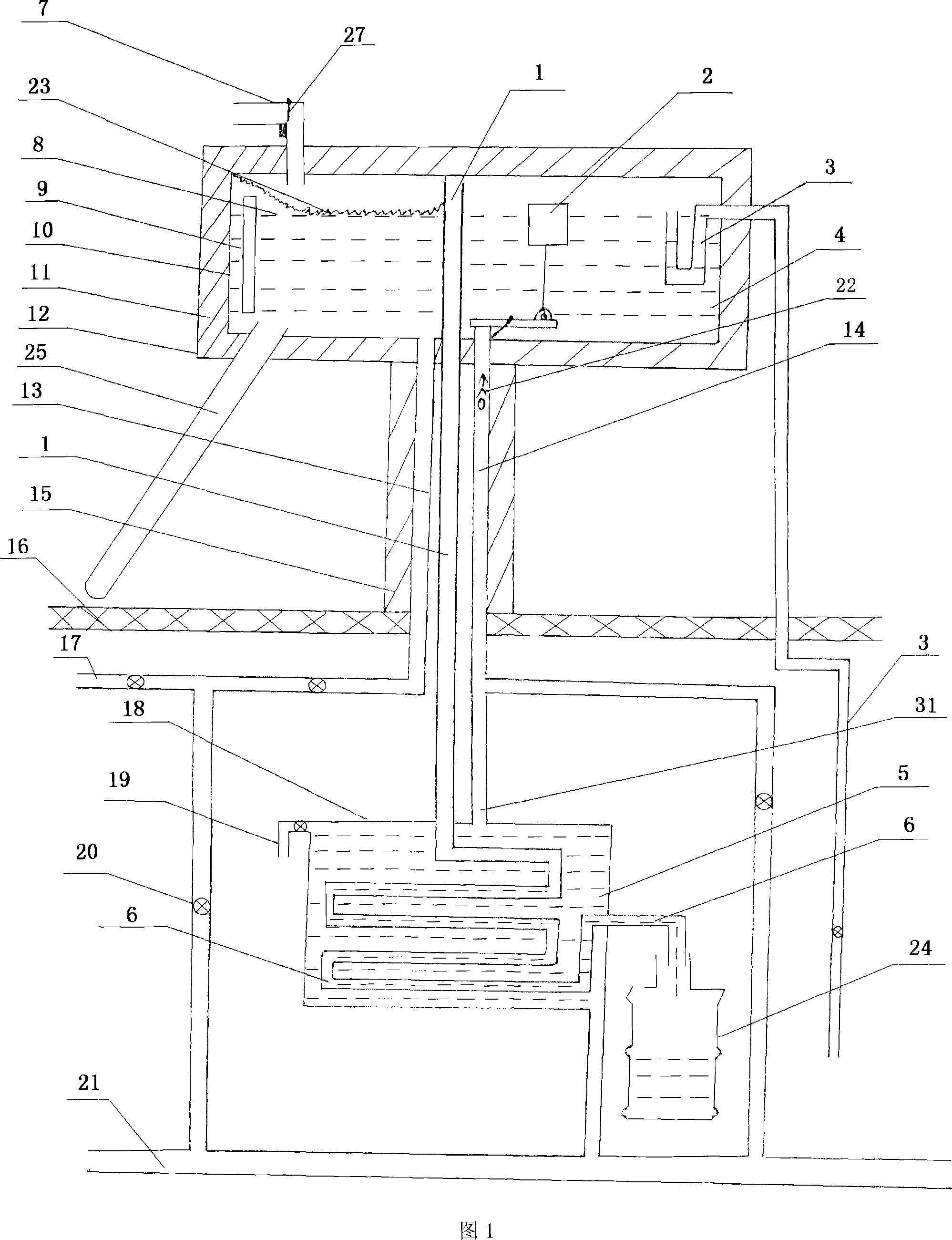
[0053] Embodiment 1: in conjunction with accompanying drawing 1, with domestic type, integrated solar water heater (hot water outlet pipe, upper water pipe are the same water supply and intake pipeline under normal circumstances, sometimes also can be two, present embodiment is two ) as an example to further describe the present invention:
[0054] The thermal insulation water storage tank 12 is composed of the inner tank 10 of the thermal insulation storage tank and the interlayer insulation material 11 of the thermal insulation storage tank. There is at least one water vapor inlet connected to the inner cavity of the thermal insulation water storage tank 12 at the highest position or near the highest position of the inner tank 10 of the thermal insulation water storage tank, and the water vapor inlet of the water vapor collection and drainage pipeline is connected to the inner cavity of the thermal insulation water storage tank. The connected inlet and exhaust ports, water v...
Embodiment 2
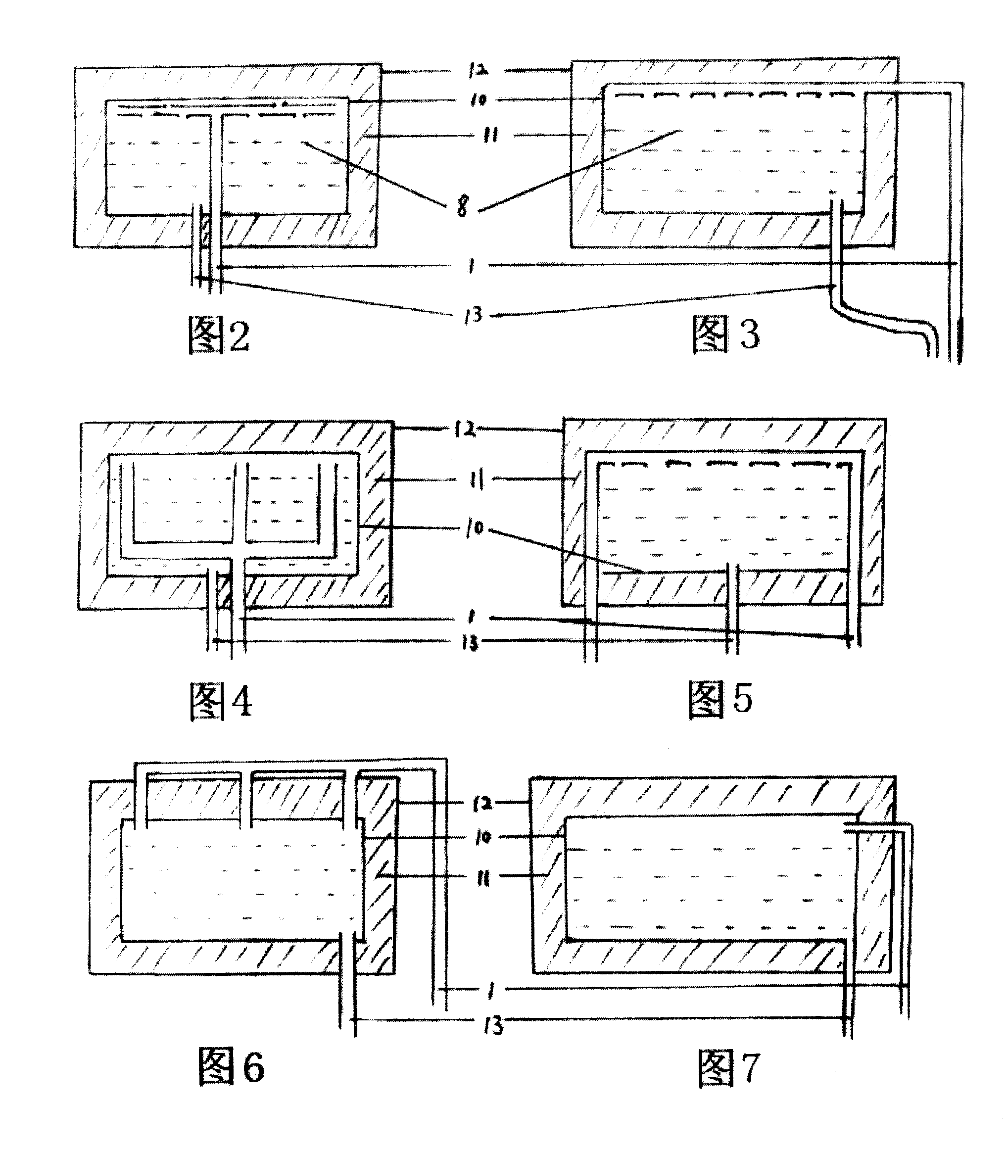
[0062] Embodiment 2: With reference to accompanying drawing 2, take the hot water outlet pipe and the upper water pipe as the same water supply and intake pipeline as an example to further describe the thermal insulation water storage tank of the present invention: a water vapor storage tank is provided in the inner cavity of the thermal insulation water storage tank 12 The collection and drainage pipeline 1, the water vapor collection and drainage pipeline is provided with a plurality of water vapor air inlets on the top of the inner tank 10 of the heat preservation water storage tank to communicate with the inner cavity of the heat preservation water storage tank 12 .
Embodiment 3
[0063] Embodiment 3: With reference to accompanying drawing 3, take the hot water outlet pipe and the upper water pipe as the same water supply and intake pipeline as an example to further describe the thermal insulation water storage tank of the present invention: a water vapor storage tank is provided outside the inner tank 10 of the thermal insulation storage tank The collection and drainage pipeline 1 is located in the interlayer insulation material 11 of the heat preservation water storage tank. The water vapor collection and drainage pipeline is provided with a plurality of water vapor inlets on the top of the heat preservation water storage tank liner 10 to communicate with the inner cavity of the heat preservation water storage tank 12.
PUM
 Abstract
Description
Claims
Application Information
 - R&D
- Intellectual Property
- Life Sciences
- Materials
- Tech Scout
- Unparalleled Data Quality
- Higher Quality Content
- 60% Fewer Hallucinations
Browse by: Latest US Patents, China's latest patents, Technical Efficacy Thesaurus, Application Domain, Technology Topic, Popular Technical Reports.
© 2025 PatSnap. All rights reserved.Legal|Privacy policy|Modern Slavery Act Transparency Statement|Sitemap|About US| Contact US: help@patsnap.com