Device and method for measuring and controlling speed of microfluid fluorescence of fluorescence PCR microcurrent control chip

A microfluidic chip and microfluidic technology, which is applied in the fields of biology, analytical chemistry and medical detection, can solve the problems that real-time feedback and flow rate control cannot be realized.

Inactive Publication Date: 2008-06-18
BEIJING UNIV OF TECH
View PDF0 Cites 23 Cited by
  • Summary
  • Abstract
  • Description
  • Claims
  • Application Information

AI Technical Summary

Problems solved by technology

[0010] The purpose of the present invention is to overcome the defects that the existing microfluidic flow rate measurement methods need to add traces of substances, so that real-time feedback and flow rate control of the actual working fluid and medium flow rate in the microchannel cannot be realized, and a new method is provided. A fluorescent PCR microfluidic chip microfluidic fluorescence speed measurement and speed control device and method. The device can measure the actual working flow velocity of the microfluid in the microchannel in real time, and can control the flow velocity according to the measurement results to make it as close as possible to the theoretical flow rate. The design flow rate is consistent, so as to ensure the smooth completion of the whole process and steps of analysis and inspection

Method used


Image

  • Device and method for measuring and controlling speed of microfluid fluorescence of fluorescence PCR microcurrent control chip
  • Device and method for measuring and controlling speed of microfluid fluorescence of fluorescence PCR microcurrent control chip

Examples


Embodiment Construction

[0036] This embodiment will be described in detail below in conjunction with accompanying drawings 1-2.

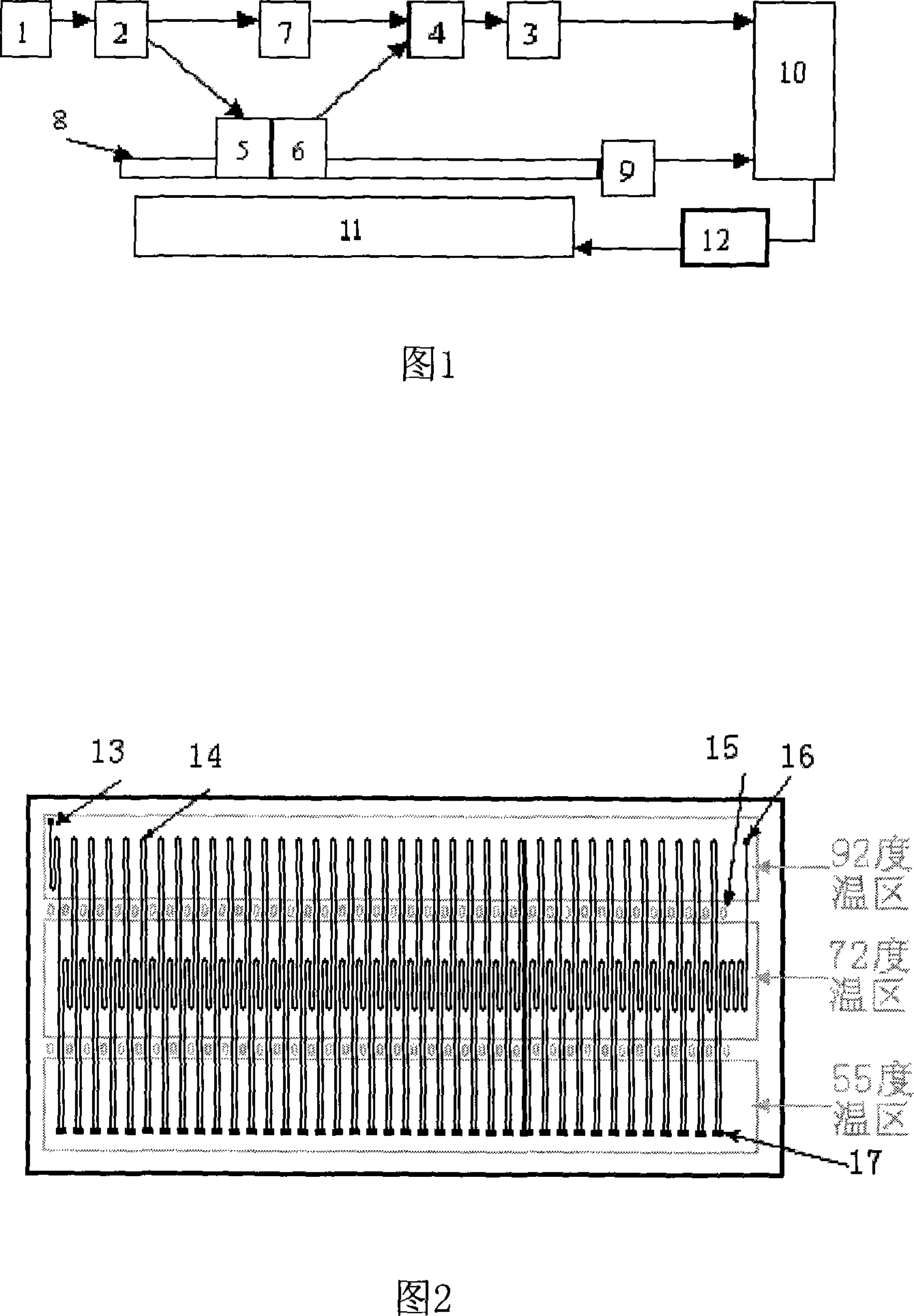
[0037] The schematic block diagram of the structure of this embodiment is shown in Figure 1, the excitation light fiber transmission system 5 and the emission light fiber transmission system 6 are fixed on the lead screw 9, the computer 10 controls the movement of the lead screw 8 through the stepping motor 9, and the flow rate control actuator 12 The input end is connected with the computer 10, and the output end is connected with the biological PCR fluorescent reagent inlet 13 of the microchannel of the biological PCR microfluidic chip. The excitation light emitted from the light source 1, through the excitation light splitting system 2 and the excitation light fiber transmission system 5, can reach the biological PCR fluorescent microfluidic chip 11 of 39 cycles (its front view is shown in Figure 2) for PCR amplification cycle Fluorescent excitation of microchannels. T...


PUM


Abstract

The invention relates to a micro-fluid fluorescence speed measurement and control device with a fluorescence PCR micro-fluidic control chip and a method thereof. The invention belongs to the detection field of biology, analytical chemistry and medicine. The invention comprises an illuminant (1), an exciting light splitting system (2), an emitted light splitting system (4), a flow speed regulation and control actuator, a photoelectric detector connected with a computer (3), a lead screw and a stepping motor connected with the lead screw. A check point is arranged at the same position of each Microchannel of a biologic PCR fluorescence microfluidic control chip, respectively. An exciting light optical fiber conducting system and an emitted light optical fiber conducting system are fixed on the lead screw. The computer controls the movement of the lead screw through the stepping motor; the input end of the speed flow regulation and control actuator is connected with the computer; the output end of the flow speed regulation and control actuator is connected with the Microchannel of the biologic PCR microfludic control chip. The device can measure the flow speed of each Microchannel, and the computer can adjust and control the flow speed of the next Microchannel through the flow speed regulation and control actuator according to the difference between the actual speed and the theoretic speed.

Description

technical field [0001] The invention relates to a fluorescent PCR (polymerase chain reaction) microfluidic chip microfluidic fluorescent speed measuring and speed control device and method, which is mainly used for measuring the working microfluidic flow rate in the microchannel of the biological fluorescent PCR microfluidic chip, to achieve The purpose of controlling actual microfluidic flow rates falls within the fields of biology and analytical chemistry and medical testing. Background technique [0002] The concept of Micro Total Analysis System (Miniaturized Total Analysis System, μ-TAS) was first proposed in the early 1990s. In the following ten years, this field has developed into one of the most cutting-edge scientific and technological fields in the world. The concept of μ-TAS is to realize the structural integration of the whole analysis process of biochemical analysis technology on the basis of the function miniaturization of many processes and steps of biochemica...

Claims


Application Information

Patent Timeline
Patent Type & Authority Applications(China)
IPC IPC(8): G01N21/64G01P5/26G05D13/00
Inventor 吴坚任艺李海亮
Owner BEIJING UNIV OF TECH
Why Eureka
Try Eureka