Method for making radial direction orientation permanent ferrite rotor

A permanent magnet ferrite and manufacturing method technology, applied in the manufacture of stator/rotor body, inorganic material magnetism, etc., can solve the problems of complex process, material waste, long working hours, etc., reduce raw material loss, improve work efficiency, and improve magnetic properties Can effect

Inactive Publication Date: 2008-06-18
许正民
View PDF0 Cites 13 Cited by
  • Summary
  • Abstract
  • Description
  • Claims
  • Application Information

AI Technical Summary

Problems solved by technology

[0010] The disadvantages of the above-mentioned traditional crafts are: complex crafts, waste of materials, long working hours

Method used


Image

  • Method for making radial direction orientation permanent ferrite rotor
  • Method for making radial direction orientation permanent ferrite rotor
  • Method for making radial direction orientation permanent ferrite rotor

Examples


Embodiment

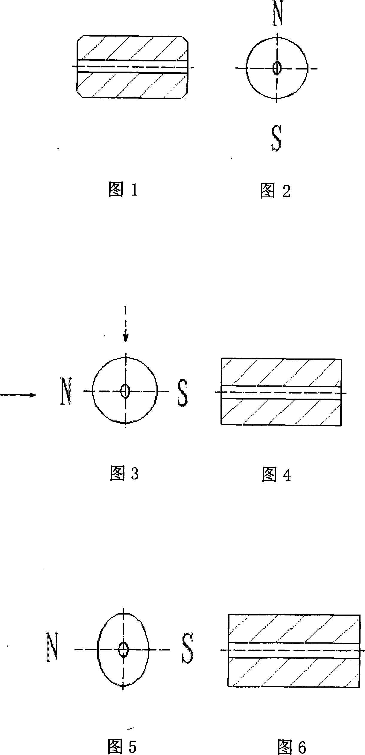
[0041] Take φ19 series products as an example. After firing, the minimum outer diameter process requirement is φ19.7. The structure is shown in Figure 1 and Figure 2, which is barrel-shaped.

[0042] Traditional method: as shown in Figure 3 and Figure 4, the traditional cylindrical blank is φ26, and the linear shrinkage ratio is X 1 , X 2 The middle values ​​are 1.32 and 1.16 respectively.

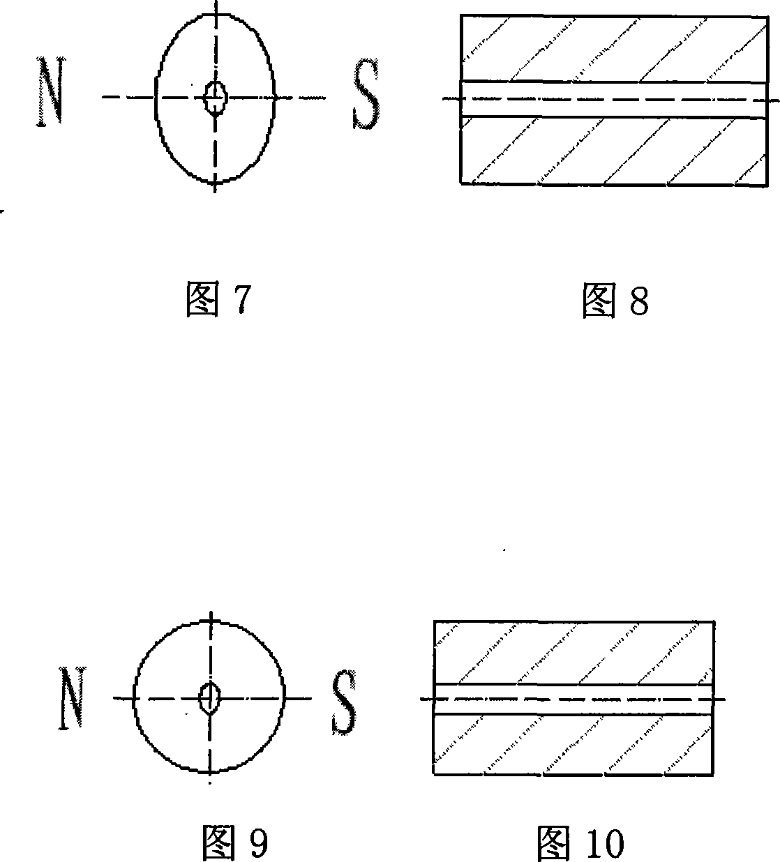
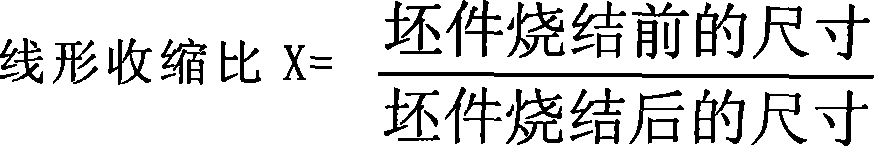
[0043] After sintering, the elliptical blank is shown in Figure 5 and Figure 6, and the minor axis of the orientation direction is:

[0044]

[0045] The major axis of the non-orientation direction is:

[0046]

[0047] Error Δ=2a-2b=22.4-19.7=2.71

[0048] The blank produced in this way not only increases the material consumption, but also increases the processing difficulty.

[0049] Forming method of the present invention: as shown in Fig. 7, Fig. 8, its blank is ellipse, after design sintering, it is certain value E=φ19.7 after shrinking in each direction

[0050] Orientat...


PUM


Abstract

The invention discloses a manufacture method of a permanent magnetic ferrite rotor with radial orientation. The invention is made by the processes of powder making, green body pressing, sintering, grinding, cleaning and classification, injection and magnetizing; the pressed green body is pressed into a cylinder with elliptic section according to different linear shrinkage ratio of alignment direction and non-alignment direction in the sintering process of the permanent magnetic ferrite with radial orientation; the cylinder has the cylindrical shape after being sintered. The invention has the advantages that the produced blank pieces overcome the defects of the round pressing process; the pressed blank pieces are contracted into round shape after being sintered; the round blank piece brings a plurality of convenience for the grinding process, improves the working efficiency of the grinding process, improves magnetic performance and reduces the loss of raw material.

Description

technical field [0001] The invention relates to a radially oriented permanent ferrite magnetic rotor, in particular to a manufacturing method of a radially oriented permanent ferrite magnetic rotor. Background technique [0002] The radially oriented permanent magnet ferrite rotor is the core component of various permanent magnet micro-motors, and its product structure is shown in Figure 1 and Figure 2. Strontium ferrite calcined powder is used as raw material, and it is made through powder making-green body pressing-sintering-grinding-cleaning and sorting-injection molding-magnetization packaging. Wherein the green body pressing-sintering-grinding process is to use a mold to press the green body into a cylindrical shape as shown in Figure 3 and Figure 4. Due to the different degrees of orientation and shrinkage stress, the actual measurement shows that the shrinkage law basically conforms to the law of ellipse mathematics, that is, [0003] x ...

Claims


Application Information

Patent Timeline
Patent Type & Authority Applications(China)
IPC IPC(8): H02K15/03H01F1/10C04B35/64
CPCY02P80/30
Inventor 张绍生
Owner 许正民
Why Eureka
Try Eureka