
Dual-rotor rotary compressor

A rotary compressor and double-rotor technology, applied to rotary piston/swing piston pump components, elastic fluid rotary piston/swing piston pump combinations, mechanical equipment, etc., can solve the problem of affecting the compressor Life, reduce compressor performance, increase exhaust resistance and other issues, to achieve the effect of reducing refrigerant leakage, improving refrigeration capacity and prolonging service life

Inactive Publication Date: 2008-07-02
LG ELECTRONICS (TIANJIN) APPLIANCES CO LTD
View PDF0 Cites 12 Cited by
  • Summary
  • Abstract
  • Description
  • Claims
  • Application Information

AI Technical Summary

Problems solved by technology

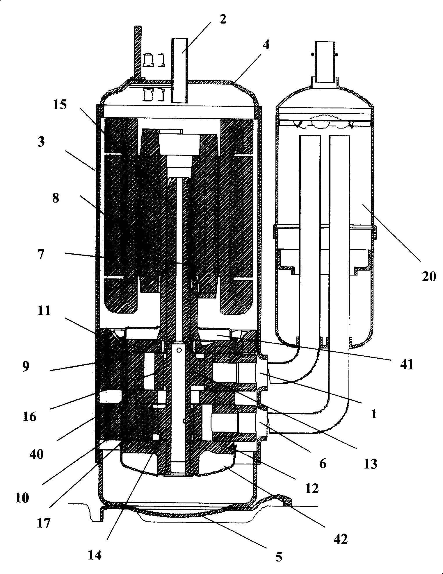
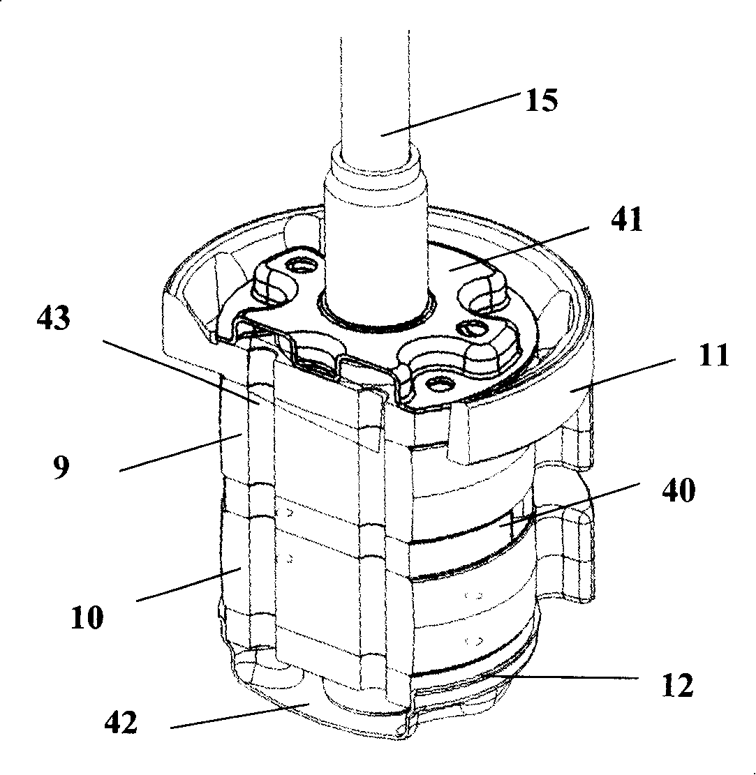
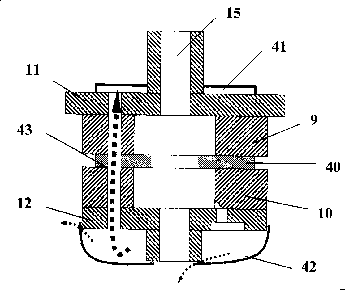
However, there are the following problems in this prior art dual-rotor rotary compressor: since the lower muffler 42 is made by stamping method, there are more or less gaps in the connecting portion between it and the lower bearing 12, so A small part of the refrigerant discharged from the lower bearing exhaust port on the lower bearing 12 to the inside of the lower muffler 42 will flow into the lower part of the shell 3 through these gaps, and at the same time, the lubricating oil at the bottom of the shell 3 will also enter the lower muffler through the gaps. 42, so that not only will the performance of the compressor decrease due to refrigerant leakage, but also the oil accumulation inside the lower muffler 42 will increase the exhaust resistance
In addition, as mentioned above, since the refrigerant compressed in the lower cylinder 10 needs to be discharged to the upper part of the casing 3 through the exhaust passage 43, the refrigerant discharge path is tortuous and the stroke is long, which will undoubtedly reduce the performance of the compressor.
In addition, since part of the refrigerant flows into the bottom of the casing 3, it will be difficult for the oil absorber installed at the lower end of the crankshaft 15 to absorb oil upwards, so the parts that cooperate with each other in the electromechanical part and the compression mechanical part will cause increased wear due to lack of oil. , thereby affecting the life of the compressor

Method used


Image

  • Dual-rotor rotary compressor
  • Dual-rotor rotary compressor
  • Dual-rotor rotary compressor

Examples


Embodiment Construction

[0016] like Figure 4 ~ Figure 7 and figure 1As shown, the double-rotor rotary compressor provided by the present invention includes an airtight container, an electric mechanical part and a compression mechanical part; wherein the airtight container is provided with two refrigerant input pipes connected to the refrigerant inlet pipeline on the liquid storage tank 20 on one side. 1, 6, and a cylindrical shell 3 filled with lubricating oil at the bottom, an upper cover 4 and a lower cover 5 with a refrigerant discharge port 2 in the center; the electromechanical part located on the upper part of the airtight container is mainly fixed on the cylinder The stator 7 on the inner wall of the shaped housing 3 and the rotor 8 which is located at the center of the stator 7 and can rotate through the electromagnetic interaction with the stator 7; The cylinder refrigerant inlet of the cylinder is connected with the refrigerant input port 1 on the shell 3, and the upper cylinder 9 with th...


PUM


Abstract

Disclosed is a double-rotor rotary compressor which comprises a closed container, an electric machinery part and a compressing machinery part. A cooling medium outlet on a lower cylinder of the compressing machinery part is composed of a radial vent hole which extends outward along the radial direction from an upper end of an inner circumferential wall thereof, a vent groove which protrudes inward from an upper end of the lower cylinder and an axial vent hole which perforates downward from a rear end of the vent groove and whose bottom end is communicated with the rear end of the radial vent hole. The double-rotor rotary compressor changes the exhaust mode of the lower cylinder from downward exhaust mode to upward exhaust mode, thus a vent on a lower bearing is unnecessary to be processed, and a lower muffler can be removed, thereby the amount of parts, processing procedures, leakage of cooling medium and production cost can be reduced, and refrigeration performance of the cooling medium can be improved. In addition, since the cooling medium discharged from the lower cylinder can be directly discharged upward, exhaust resistance is weak, and stroke is comparatively shorter, thereby performance of the compressor can be improved.

Description

technical field [0001] The invention relates to a double-rotor rotary compressor, in particular to a double-rotor rotary compressor which can reduce refrigerant leakage and exhaust resistance, thereby improving product performance. Background technique [0002] In general, a compressor is a machine that compresses a fluid. This type of compressor is composed of a closed container with a certain internal space, an electromechanical part installed in the closed container and capable of generating driving force, and a compression mechanical part capable of compressing fluid by using the driving force of the electromechanical part. figure 1 It is a cross-sectional view of the longitudinal structure of a dual-rotor rotary compressor in the prior art. figure 2 for figure 1 Shown is a sectional perspective view of the local structure of the compression mechanism in the dual-rotor rotary compressor. image 3 for figure 1 It is a cross-sectional view of the longitudinal structur...

Claims


Application Information

Patent Timeline
Patent Type & Authority Applications(China)
IPC IPC(8): F04C23/00F04C29/12
Inventor 王海龙
Owner LG ELECTRONICS (TIANJIN) APPLIANCES CO LTD
Learn More