Forced oscillation direct-action power generation, buffering accumulated energy and electric drive automobile

A technology of automobile and stroke, which is applied in the field of automobile, can solve the problems of reducing engine efficiency, small intake air volume, low compression ratio, etc., and achieve the effect of facilitating the number of working cylinders, reducing mechanical loss and improving work efficiency

Inactive Publication Date: 2008-07-09
TIANJIN CHANGING POWER TECH
View PDF0 Cites 13 Cited by
  • Summary
  • Abstract
  • Description
  • Claims
  • Application Information

AI Technical Summary

Problems solved by technology

[0002] The currently known and commonly used automobile power system is a four-stroke gasoline or diesel engine, which drives the wheels to rotate through a transmission, a transmission shaft, etc., and has a fixed compression ratio. The ratio changes, especially at low speeds, the intake air volume is small, the compression ratio is low, the efficiency is low, and the mechanical friction loss ratio of the engine at low speed is large, which further reduces the engine efficiency. At present, there are four main methods to improve fuel efficiency. The mechanical device changes the compression ratio to optimize the real compression ratio of the gas and increase the efficient operating range of the engine; the second is a hybrid vehicle, which mainly includes a low-power engine, a generator, a battery and an electric motor. Run in the efficiency range to improve fuel efficiency, generate power when parking or at low speed and store it in the battery, when the power demand is low, the battery and the motor provide driving force, and when the power demand is high, the engine or the engine and the motor jointly provide driving force; the third is pure Electric vehicles; the fourth is fuel cell vehicles; the four methods to improve fuel efficiency have not been used on a large scale due to factors such as reliability and cost

Method used


Image

  • Forced oscillation direct-action power generation, buffering accumulated energy and electric drive automobile
  • Forced oscillation direct-action power generation, buffering accumulated energy and electric drive automobile
  • Forced oscillation direct-action power generation, buffering accumulated energy and electric drive automobile

Examples


Embodiment Construction

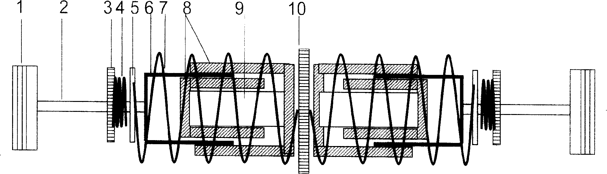
[0020] exist figure 1 Among them, the permanent magnet (9) (or excitation magnet) is connected with the high-permeability body (8), forming a magnetic field in which the magnetic field lines are distributed radially between the high-permeability, the piston (1) and the connecting rod (2), the force plate (5), the moving coil (6), the spring (7) is connected, the other end of the spring (7) is connected with the spring seat (10), the spring (4) is connected with the spring seat (3), and the spring seat (3) is fixed on the body , the central opening is slidably connected with the connecting rod (2). The piston (1), spring (4) and spring (7) form a vibrating system, the reciprocating motion of the piston (1) drives the driving coil (6) to reciprocate in the magnetic field, and the balance position of the piston is near the top dead center of the cylinder.

[0021] Normal operation is divided into four strokes, the first stroke, the intake stroke, the intake valve is opened, the ...


PUM


Abstract

The invention discloses a vehicle system of optimizing the compression ratio of a motor, reducing the mechanical losses, enhancing the fuel efficiency under the wide range of conditions. The vehicle system can directly uses the line movement of the plug of a reciprocate motor to drive a coil or a magnet to produce current to generate. The plug and the coil (or) use a mechanical spring((or a magnet) to form a vibration system; during the non working stroke process, the plug is driven by the magnetic force of the vibration system and the coil; the current produced by a generator drives the motor to move via the current buffering; the vehicle system realizes the optimization of the plug stroke and the compression ratio via controlling the coil current of the generator by a controlling center; the power is adjusted by controlling the air inlet volume via controlling operating cylinders numbers and inlet air stroke distance; the driving of a gas gate also use the magnetic vibration system (or the mechanical vibration system ) and the magnetic force to force the air gate to open and close correctly, thus supplementing the energy of a forced vibration system by using the magnetic force; the vehicle system can conveniently adjust the compression ratio and suit for the compression-igniti work of a plurality of fuels.

Description

technical field [0001] The invention relates to an energy-saving automobile system, in particular to a motor-driven automobile that adopts vibration direct motion power generation, buffer energy storage and motor drive. Background technique [0002] The currently known and commonly used automobile power system is a four-stroke gasoline or diesel engine, which drives the wheels to rotate through a transmission, a transmission shaft, etc., and has a fixed compression ratio. The ratio changes, especially at low speeds, the intake air volume is small, the compression ratio is low, the efficiency is low, and the mechanical friction loss ratio of the engine at low speed is large, which further reduces the engine efficiency. At present, there are four main methods to improve fuel efficiency. The mechanical device changes the compression ratio to optimize the real compression ratio of the gas and increase the efficient operating range of the engine; the second is a hybrid vehicle, w...

Claims


Application Information

Patent Timeline
Patent Type & Authority Applications(China)
IPC IPC(8): B60K6/28B60K6/46B60L11/02H02K7/18B60L50/10
CPCY02T10/62Y02T10/64Y02T10/7072
Inventor 唐明龙
Owner TIANJIN CHANGING POWER TECH
Why Eureka
Try Eureka