An electric spindle design adopting electromagnetism anti-thrusting and air static pressure radial bearing support

A technology of thrust bearings and radial bearings, applied in the field of machinery, can solve problems such as rotor creep, high bearing height, and excessive vibration of the electric spindle shaft system, and achieve the effects of simple processing technology, high dynamic balance precision, and simple processing

Inactive Publication Date: 2008-07-09
LUOYANG BEARING SCI & TECH CO LTD
View PDF0 Cites 5 Cited by
  • Summary
  • Abstract
  • Description
  • Claims
  • Application Information

AI Technical Summary

Problems solved by technology

[0002] In the PCB plate drilling processing industry, because the drilling diameter is getting smaller and smaller, the production efficiency requirements are getting higher and higher. Therefore, in order to meet this need, the speed requirements of the electric spindle for PCB drilling are also getting higher and higher, and Ordinary PCB electric spindle structure is no longer suitable for ultra-high speed, especially the support of the electric spindle shaft system no longer matches the ultra-high-speed motor system, because:
[0003] 1. Because the DmN value of the bearing is too high, and the industry requires that the electric spindle cannot be lubricated by oil mist or oil and air, the traditional rolling element bearing cannot be applied;
[0004] 2. The rotor of the traditional electric spindle motor adopts the structure of cast aluminum with magnetic steel sheet. Because the linear speed of the rotor surface is too high, and the structural strength and conductivity of the aluminum alloy strip are low, it is easy to cause the rotor to creep under the ultra-high speed state, causing the electric spindle The vibration of the shaft system is too large, which affects the processing quality of the spindle

Method used


Image

  • An electric spindle design adopting electromagnetism anti-thrusting and air static pressure radial bearing support

Examples


Embodiment Construction

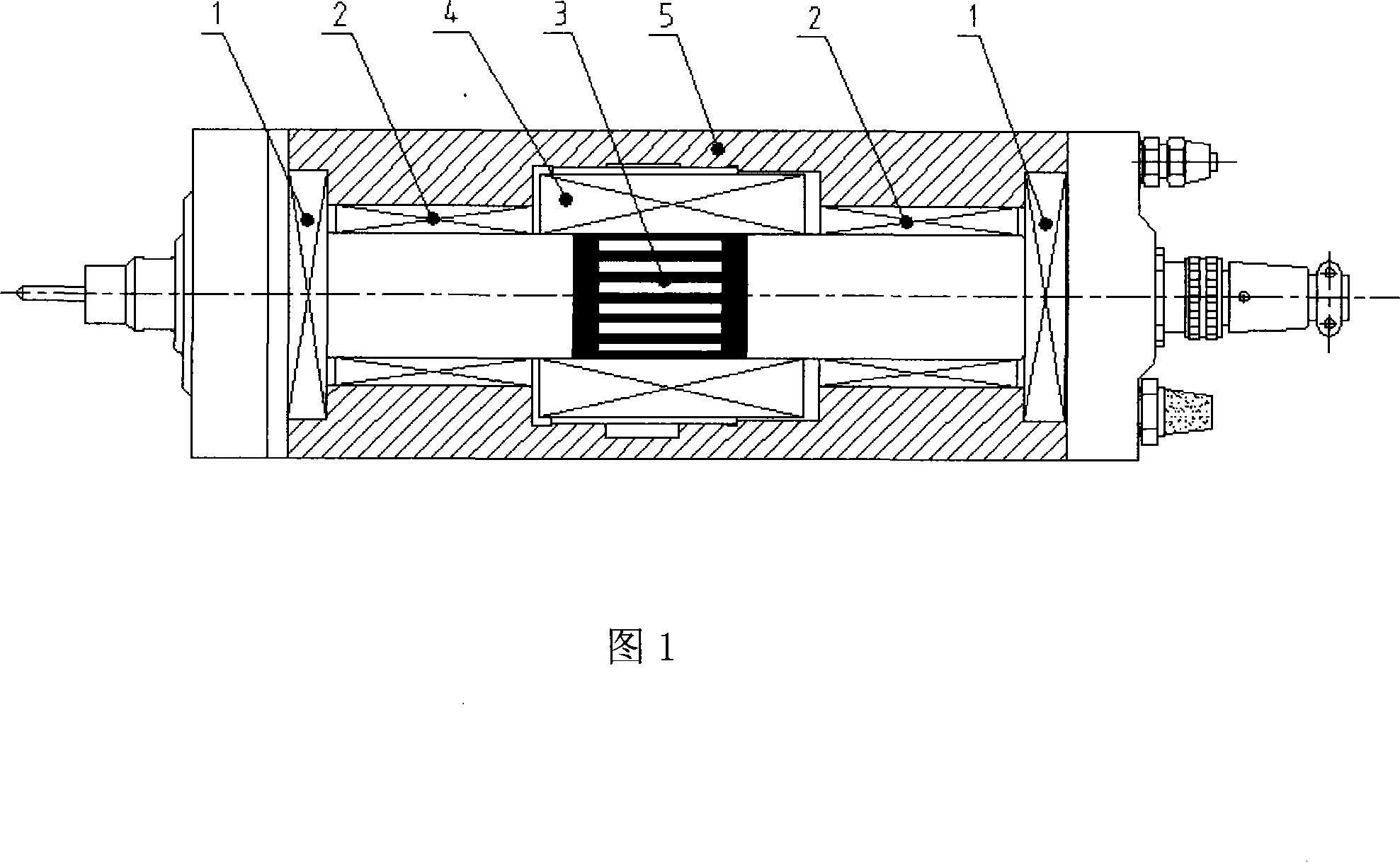
[0015] As shown in Figure 1, the design of the electric spindle adopting electromagnetic thrust and pneumatic radial bearing support of the present invention, according to the external dimension limitation and rigidity requirements of the electric spindle, electromagnetic stoppers are arranged at both ends of the electric spindle housing (5). Push bearings (1), the configuration of both ends can eliminate the electromagnetic interference between the two electromagnetic thrust bearings (1), and is also conducive to the design and concentration of power supply lines for the electromagnetic thrust bearings (1), ensuring the rotor-shaft integrated shafting (3) axial rigidity; aerostatic radial bearings (2) are symmetrically arranged on both sides of the electric spindle housing (5) to support the rotor-rotating shaft integrated shafting (3), and the symmetrically arranged aerostatic radial bearings (2) The radial bearing (2) can reduce the vibration of the rotor-rotating shaft inte...


PUM


Abstract

The invention relates to an electric spindle design adopting an electromagnetic anti-thrust and a radial bearing support. According to the outline dimension limit and the stiffness requirement of the electric spindle, the two ends inside a shell (5) of the electric spindle is provided with an electromagnetic anti-thrust bearing (1), which eliminates the electromagnetic interference between the two ends, is beneficial for the design and concentration of the power supply line of the electromagnetic anti-thrust bearing and ensures the radial stiffness of a rotor-rotating shaft integrated shaft system (3). The two sides inside the shell of the electric spindle are symmetrically provided with aerostatic pressure radial bearings (2) so as to support the shaft system (3). The symmetric aerostatic pressure radial bearings can reduce the vibration of the shaft system when the electric motor is in the state of operation with super high speed and ensure the radial stiffness. The rotor-rotating shaft integrated shaft system makes the squirrel-cage bar of the rotor of the electric motor and the rotating shaft into an integrated structure and the corresponding position of a stator (4) arranged in the middle section and the shell of the electric spindle, that is the position of the squirrel-cage bar, adopts copper alloys directly welded in a groove to reduce the creep deformation of the rotor bar, reduce the vibration value of the shaft system and improve the power rate and the structural strength.

Description

technical field [0001] The invention belongs to the technical field of machinery, and in particular relates to a design of an electric spindle supported by an electromagnetic thrust and an air static pressure radial bearing. Background technique [0002] In the PCB plate drilling processing industry, because the drilling diameter is getting smaller and smaller, the production efficiency requirements are getting higher and higher. Therefore, in order to meet this need, the speed requirements of the electric spindle for PCB drilling are also getting higher and higher, and Ordinary PCB electric spindle structure is no longer suitable for ultra-high speed, especially the support of the electric spindle shaft system no longer matches the ultra-high-speed motor system, because: [0003] 1. Because the DmN value of the bearing is too high, and the industry requires that the electric spindle cannot be lubricated by oil mist or oil and air, the traditional rolling element bearing can...

Claims


Application Information

Patent Timeline
Patent Type & Authority Applications(China)
IPC IPC(8): H02K7/09H02K7/08H02K5/16H02K3/04H02K17/16F16C32/04F16C32/06
Inventor 陈长江徐同申邱宪国肖汝峰傅广森郭丽娟田民黄昆俞蓬
Owner LUOYANG BEARING SCI & TECH CO LTD
Why Eureka
Try Eureka