

Decompression drying device
A technology of decompression drying device and decompression mechanism, which is applied in the directions of drying solid materials, heating to dry solid materials, and drying. Larger and other problems, to achieve the effect of rapid decompression drying treatment and heat treatment, reduced occupied area, and small waste heat
- Summary
- Abstract
- Description
- Claims
- Application Information
AI Technical Summary
Problems solved by technology
Method used
Image

Examples
Embodiment Construction
[0042] Hereinafter, preferred embodiments of the present invention will be described with reference to the accompanying drawings.
[0043] 1. The overall composition of the decompression drying device
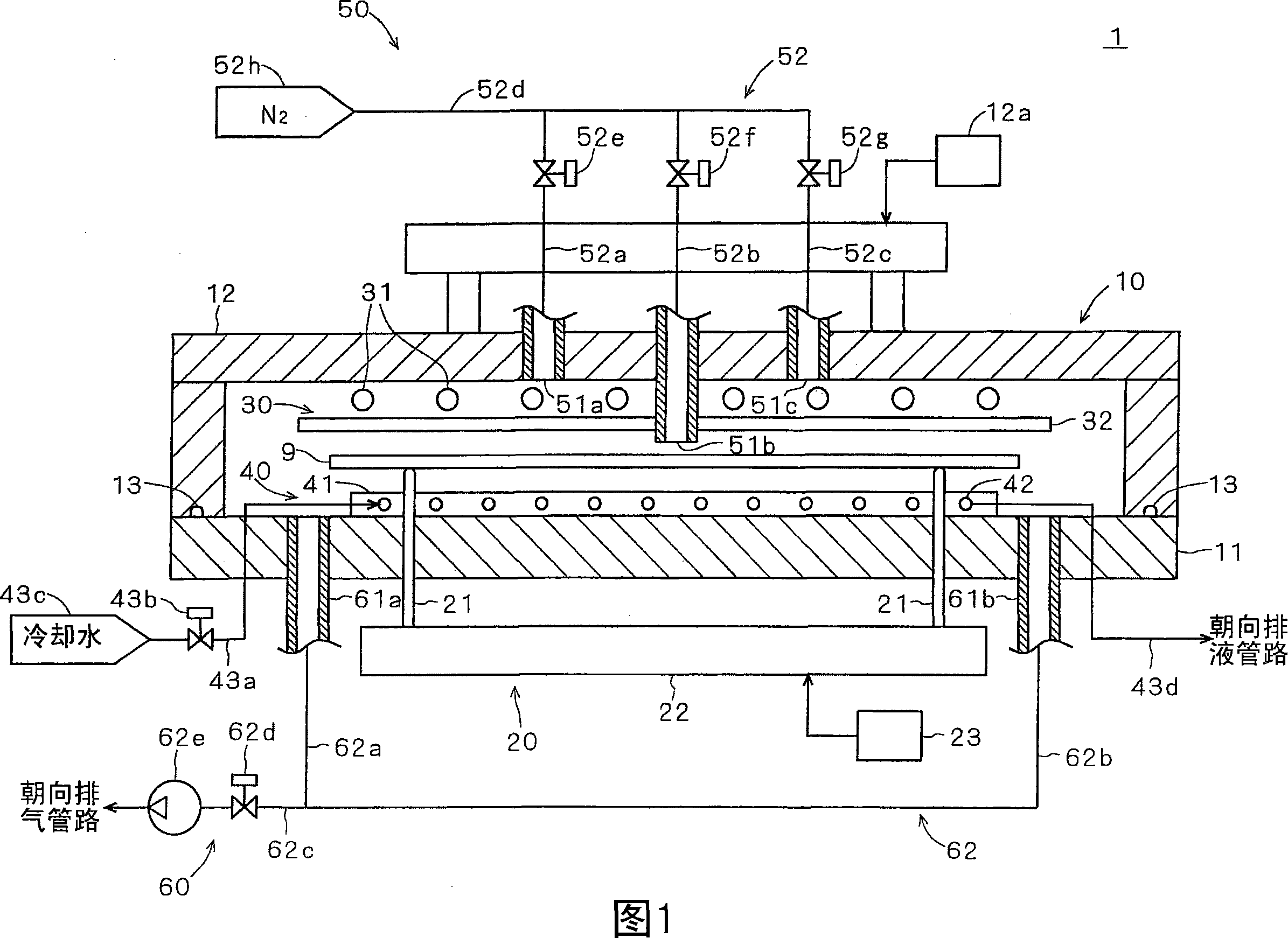
[0044] FIG. 1 is a longitudinal sectional view showing the configuration of a reduced-pressure drying apparatus 1 according to one embodiment of the present invention. FIG. 1 also schematically shows the configuration of the suction and exhaust system or drive system connected to the reduced-pressure drying device 1 . This reduced-pressure drying device 1 is used to selectively etch the surface of a rectangular glass substrate (hereinafter simply referred to as "substrate") 9 for liquid crystal display devices. Equipment for pressure drying and subsequent heating and cooling. As shown in FIG. 1 , the reduced-pressure drying apparatus 1 has a chamber 10 , a substrate holding unit 20 , a heating unit 30 , a cooling unit 40 , an air supply unit 50 , and an exhaust unit 60 .
[...
PUM
 Abstract
Description
Claims
Application Information