High-precision time synchronizing apparatus

A time synchronization device, high-precision technology, applied in synchronization, measuring devices, clocks driven by synchronous motors, etc., can solve the problems of long time for each synchronization adjustment, real-time monitoring of clock signals, etc.

Inactive Publication Date: 2008-07-30
HARBIN ENG UNIV
View PDF0 Cites 57 Cited by
  • Summary
  • Abstract
  • Description
  • Claims
  • Application Information

AI Technical Summary

Problems solved by technology

[0006] In order to solve the problems of long time for each synchronization adjustment and the inability to monitor and adjust the clock signal in real time in various existing time synchronization devices, the present invention provides a high-precision time synchronization device

Method used


Image

  • High-precision time synchronizing apparatus

Examples


specific Embodiment approach 1

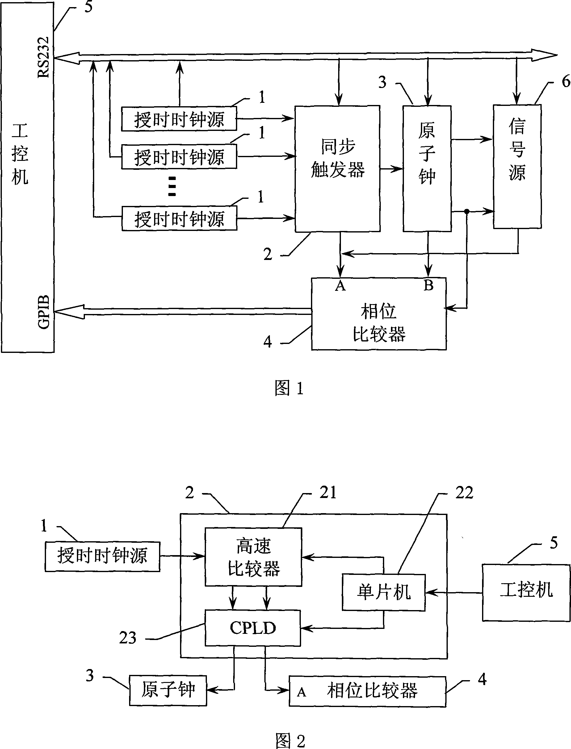
[0015] Specific implementation manner 1: The high-precision time synchronization device of this embodiment is composed of a timing clock source 1, a synchronization trigger 2, an atomic clock 3, a phase comparator 4, an industrial computer 5 and a signal source 6, wherein

[0016] The synchronization trigger 2 receives the timing signal from the timing clock source 1 and divides it into two outputs after shaping, one is output to the atomic clock 3 as the synchronization signal, and the other is output to the phase comparator 4 as the phase A input signal;

[0017] The atomic clock 3 synchronously outputs a second pulse (1PPS) signal and a frequency reference signal according to the input synchronization signal, the second pulse signal is respectively output to the phase comparator 4 as the B-phase input signal, and output to the signal source 6 as the clock reference signal; The frequency reference signal is respectively output to the phase comparator 4 as a working reference fre...

specific Embodiment approach 2

[0028] Embodiment 2: The difference between this embodiment and the high-precision time synchronization device described in Embodiment 1 is that the synchronization trigger 2 is composed of a high-speed digital comparator 21, a single-chip computer 22, and a CPLD 23. The high-speed digital comparator 21 The timing signal input by the timing clock source 1 is reshaped and divided into two identical signals and output to the CPLD23. The CPLD23 reshapes the two input signals and outputs them to the atomic clock 3 and the phase comparator 4 respectively; the single-chip 22 receives via the RS232 serial data bus According to the control signal sent by the industrial computer 5, the single-chip 22 outputs the signal to the CPLD 23 to control the CPLD 23 to output or stop the output signal to the phase comparator 4 according to the control signal.

[0029] In the synchronous trigger 2 of this embodiment, the input signal is formed into a pulse signal with a rising edge of better than 10 ...

specific Embodiment approach 3

[0032] Embodiment 3: The difference between this embodiment and the high-precision time synchronization device described in Embodiment 1 or 2 is that it also includes multiple timing clock sources 1, and the multiple timing clock sources 1 respectively output timing signals to Synchronous trigger 2, said synchronous trigger 2 selects a signal sent by time service clock source 1 according to the received selection command signal sent by industrial computer 5 for shaping and output; industrial computer 5 obtains synchronous trigger through RS232 serial communication bus 2 The frequency of the output signal of the selected channel of timing clock source 1, and when the frequency is outside the set range, the synchronization trigger 2 is sent a command to select another channel of timing clock signal.

[0033] The high-precision time synchronization device of this embodiment includes multiple timing clock sources 1, and the multiple timing clock sources 1 can be the same clock source ...


PUM


Abstract

The invention relates to a time synchronization device in a radio navigation system, in particular to a high-precision time synchronization device, which solves the problems in the prior time synchronization device including long-time synchronization adjustment and inability of real-time monitoring and adjustment of clock signal. In the device of the invention, an industrial computer obtains phase difference signal output from a phase comparator via a GPIB bus, and respectively transmits a control signal to a synchronizer trigger, an atomic clock and a signal source via a RS232 serial communication bus; and the industrial computer further controls the operating state and the switching thereof. The operating state includes time synchronization state: the phase comparator obtains the phase difference of signals output from the synchronizer trigger and the atomic clock, and the industrial computer adjusts the signal output from the atomic clock to synchronize with the signal output from the synchronizer trigger; and monitoring state: the phase comparator obtains the phase difference of signals output from the atomic clock and the signal source, and the industrial computer adjusts the signal output from the signal source to synchronize with the signal output from the atomic clock.

Description

Technical field [0001] The invention relates to a time synchronization device in a radio navigation system. Background technique [0002] The time synchronization device uses the time release system to broadcast time information to the outside world. The user terminal compares the received time information with local information, measures the time difference between the two, and synchronizes the user time with the system time. Commonly used synchronization methods are mainly short wave time service method, long wave time service method, satellite time service method, clock movement method and set up synchronization monitoring station. [0003] Shortwave time service and longwave time service use high-power shortwave and longwave radio signals to transmit time information on the ground. The propagation characteristics of shortwave and longwave determine that shortwave timing needs to transmit high-power timing signals, so the equipment is bulky and the structure is complex. The ti...

Claims


Application Information

Patent Timeline
Patent Type & Authority Applications(China)
IPC IPC(8): G01S5/14H03L7/26G04G7/02G04C11/02G04R20/04G04R40/06
Inventor 郝燕玲黄平徐定杰韦金辰沈锋薛冰王伟
Owner HARBIN ENG UNIV
Why Eureka
Try Eureka