Concentric ring type cross current type hypergravity field swinging bed device

A high-gravity field and rotating bed technology, which is applied to the concentric circle cross-flow type high-gravity field rotating bed device, desorption, reaction process, and heat exchange fields, can solve unsuitable gas-liquid heat and mass transfer occasions and insufficient mass transfer efficiency High, not suitable for large flow and other problems, to achieve the effect of high gas-liquid mass transfer efficiency, simple structure, and small equipment pressure drop

Active Publication Date: 2008-08-06
ZHEJIANG UNIV OF TECH
View PDF4 Cites 23 Cited by
  • Summary
  • Abstract
  • Description
  • Claims
  • Application Information

AI Technical Summary

Problems solved by technology

Although the current packed high-gravity field rotary bed has a relatively large processing capacity, the mass transfer efficiency is not high enough because there is only one rotor, and the gas phase flow resistance is large, and the equipment pressure drop is large, so it is not suitable for larger flow rates and mass transfer. Higher requirements for gas-liquid heat and

Method used


Image

  • Concentric ring type cross current type hypergravity field swinging bed device
  • Concentric ring type cross current type hypergravity field swinging bed device
  • Concentric ring type cross current type hypergravity field swinging bed device

Examples


Embodiment 1

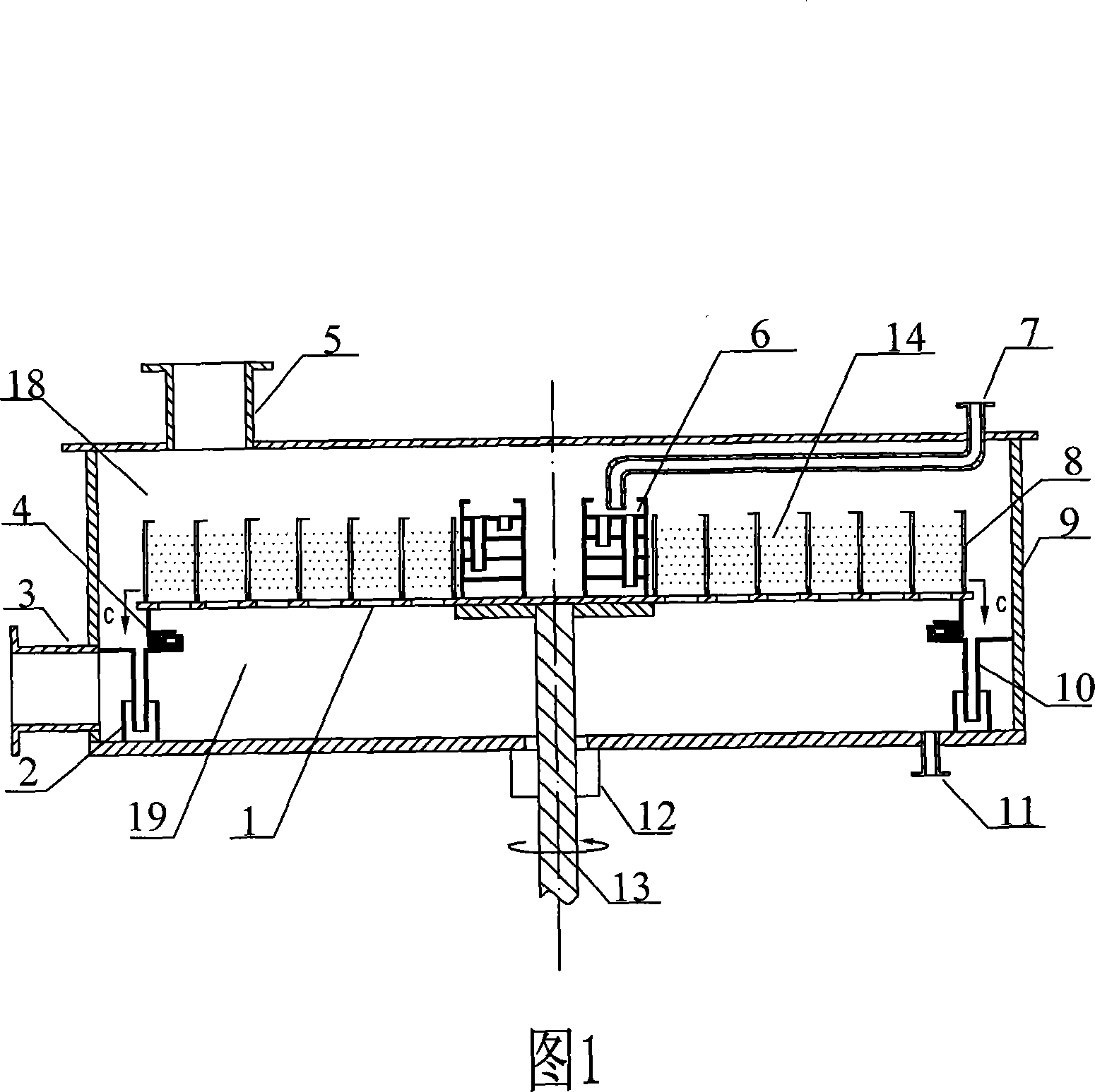
[0019] Embodiment 1: When used for desorption, the structure of the device is shown in Figure 1. The medium a is gas, and the medium c is liquid. The gas enters the inner cavity of the shell 9 from the inlet pipe 3 of the medium a, passes through the rotating disk 1, and is discharged through the outlet pipe 5 of the medium b after cross-flow contact with the medium c; the raw material is discharged from the inlet pipe 7 of the medium c After entering the liquid redistributor 6 for initial distribution, it enters the inner ring of the concentric ring 8, is thrown out by the high-speed rotating concentric ring 8 radially, and is crushed into small liquid droplets that contact the gas multiple times in cross-flow for transmission. The substance is finally discharged from the guide pipe 10 through the outlet pipe 11 of the medium d.

[0020] In the present invention, since the liquid is thrown out from the center by the rotor, it is pulverized into small liquid droplets by the co...

Embodiment 2

[0021] Embodiment 2: When used for heat exchange, the structure of the device is shown in Figure 1. The medium a is gas, and the medium c is liquid. The gas enters the inner cavity of the shell 9 from the inlet pipe 3 of the medium a, passes through the rotating disk 1, and is discharged through the outlet pipe 5 of the medium b after cross-flow contact with the medium c; the liquid is discharged from the inlet pipe 7 of the medium c After entering the liquid redistributor 6 for initial distribution, it enters the inner ring of the concentric ring 8, and is thrown out by the high-speed rotating concentric ring 8 radially, and is crushed into small liquid droplets that contact the gas multiple times in cross-flow for exchange. The heat is finally discharged from the guide pipe 10 through the outlet pipe 11 of the medium d.

[0022] In the present invention, since the liquid is thrown out from the center by the rotor, it is crushed into small liquid droplets by the concentric ci...

Embodiment 3

[0023] Embodiment 3: When the product used in the single-step gas-liquid chemical reaction is liquid or liquid and gas, the structure of the device is shown in Figure 1. Medium a is a gaseous reaction raw material, medium c is a liquid reaction raw material, the gaseous reaction raw material enters the inner cavity of the shell 9 from the inlet pipe 3 of medium a, passes through the rotating disk 1, and performs a cross-flow contact reaction with the liquid reaction raw material medium c, and the generated gas reacts The product is discharged through the medium b outlet pipe 5; the liquid reaction raw material enters the liquid redistributor 6 from the medium c inlet pipe 7 for initial distribution, and then enters the inner ring of the concentric ring 8, and is rotated by the high-speed concentric ring 8 along the radial direction. Throw it out, crush it into small liquid droplets and contact with the gas multiple times in cross-flow for reaction, mass transfer and heat transf...


PUM


Abstract

The invention relates to concentric cross-flow type rotating packed bed in high-gravity field , comprising a shell, a rotating disc, a rotating shaft and a liquid redistributor, the shell is provided with a medium a inlet pipe, a medium b outlet pipe, a medium d outlet pipe and a fluid bath, a concentric ring and the liquid redistributor are fixedly connected with the rotating disc, the center of which is in fixed connection with the rotating shaft, the end of labyrinth seal is in connection with the shell, the lower end is in connection with a guiding pipe which is inserted in the fluid bath, the labyrinth seal and the rotating disc divide the shell into an upper cavity and a lower cavity, the medium b outlet pipe is in communication with the upper cavity, the medium a inlet pipe and the medium d outlet pipe are separately in communication with the lower cavity, one end of a medium c inlet pipe is in communication with the upper end of a liquid distributor, while the other end surpasses the shell and is sealed together with the shell. The beneficial effect of the rotating packed bed is that the rotating packed bed of the invention has the simple and reasonable structure so as to be easily installed, the little gas resistance, the low equipment pressure drop, and the higher efficiency and the better effect of gas-liquid mass transfer.

Description

technical field [0001] The invention relates to a gas-liquid contact device, especially a concentric circle cross-flow type supergravity field rotating bed device, which can be widely used in gas-liquid contact in chemical industry, petrochemical industry, biochemical industry, pharmaceutical, metallurgy, light industry and other industries Occasions, especially suitable for desorption, heat exchange, reaction process. Background technique [0002] The high gravity field rotating bed is characterized by small size and high mass transfer efficiency, and is known as the "transistor" of chemical equipment. Before the present invention was made, the high-gravity field rotating beds in the prior art could be divided into two categories according to the rotor structure: single-layer high-gravity field rotating beds and multi-layer high-gravity field rotating beds. The single-layer high-gravity field rotating bed has packing type Chinese patents CN1059105A, CN1062098A, disc type C...

Claims


Application Information

Patent Timeline
IPC IPC(8): B01D3/30B01J8/10B01J19/28
Inventor 计建炳徐之超俞云良焦云强隋立堂
Owner ZHEJIANG UNIV OF TECH
Why Eureka
Try Eureka