
Three-phase electric power converter, and control device and control method of three-phase alternating current motor

A power converter and three-phase power technology, which is applied in the direction of AC motor control, electronic commutation motor control, motor generator control, etc., can solve the problems of shortened life, high manufacturing cost, and increased peak voltage of motor terminals to ground, etc. , to achieve the effect of reducing the deterioration of insulating materials

Active Publication Date: 2008-08-06
HITACHI IND PROD LTD
View PDF1 Cites 21 Cited by
  • Summary
  • Abstract
  • Description
  • Claims
  • Application Information

AI Technical Summary

Problems solved by technology

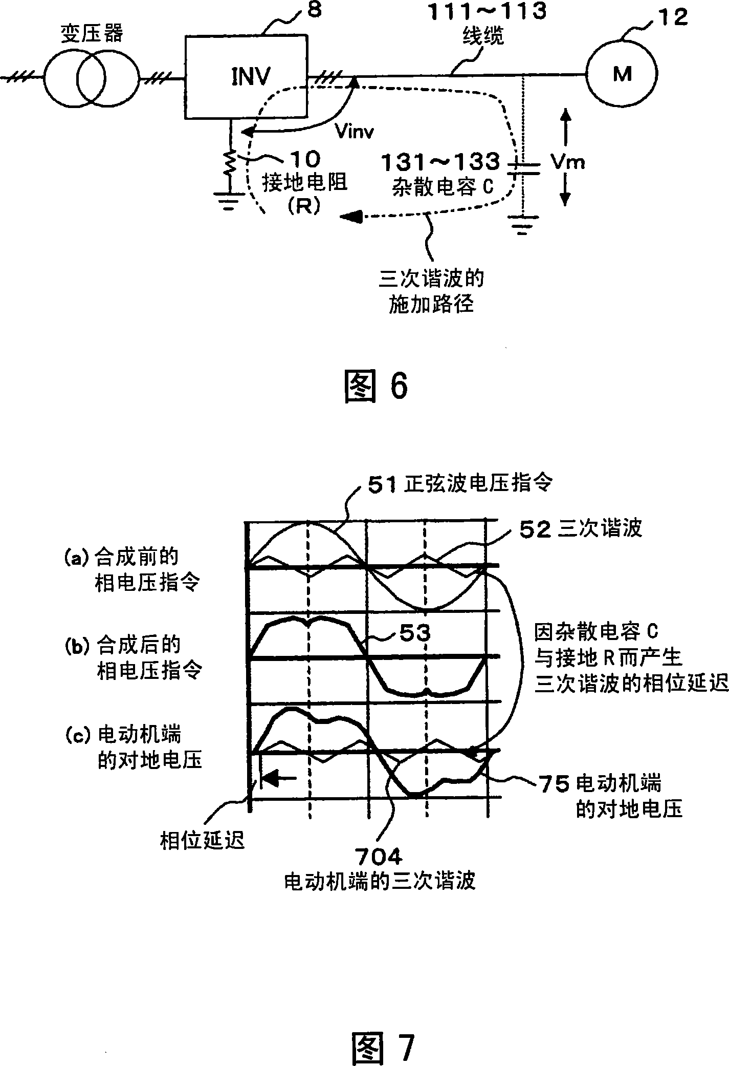
However, on the path where the third harmonic is applied to the motor terminals, there are grounding resistors of the main circuit of the power converter and electrostatic capacitances to ground of cables connecting the power converter and the motor.
Therefore, there will be a phase delay of the time constant determined by the product of the two for the sine wave voltage, and it can be seen that the waveform after the synthesis of the sine wave voltage and the third harmonic is not symmetrical. Therefore, the peak value of the ground voltage of the motor terminal raised
[0009] On the other hand, as disclosed in Non-Patent Document 1, the deterioration speed of the insulating material of the motor largely depends on the peak value of the voltage applied between the winding and the ground, so the life is shortened.
Considering this, in order to achieve insulation strengthening, there is a disadvantage of high manufacturing cost

Method used


Image

  • Three-phase electric power converter, and control device and control method of three-phase alternating current motor
  • Three-phase electric power converter, and control device and control method of three-phase alternating current motor
  • Three-phase electric power converter, and control device and control method of three-phase alternating current motor

Examples


Embodiment Construction

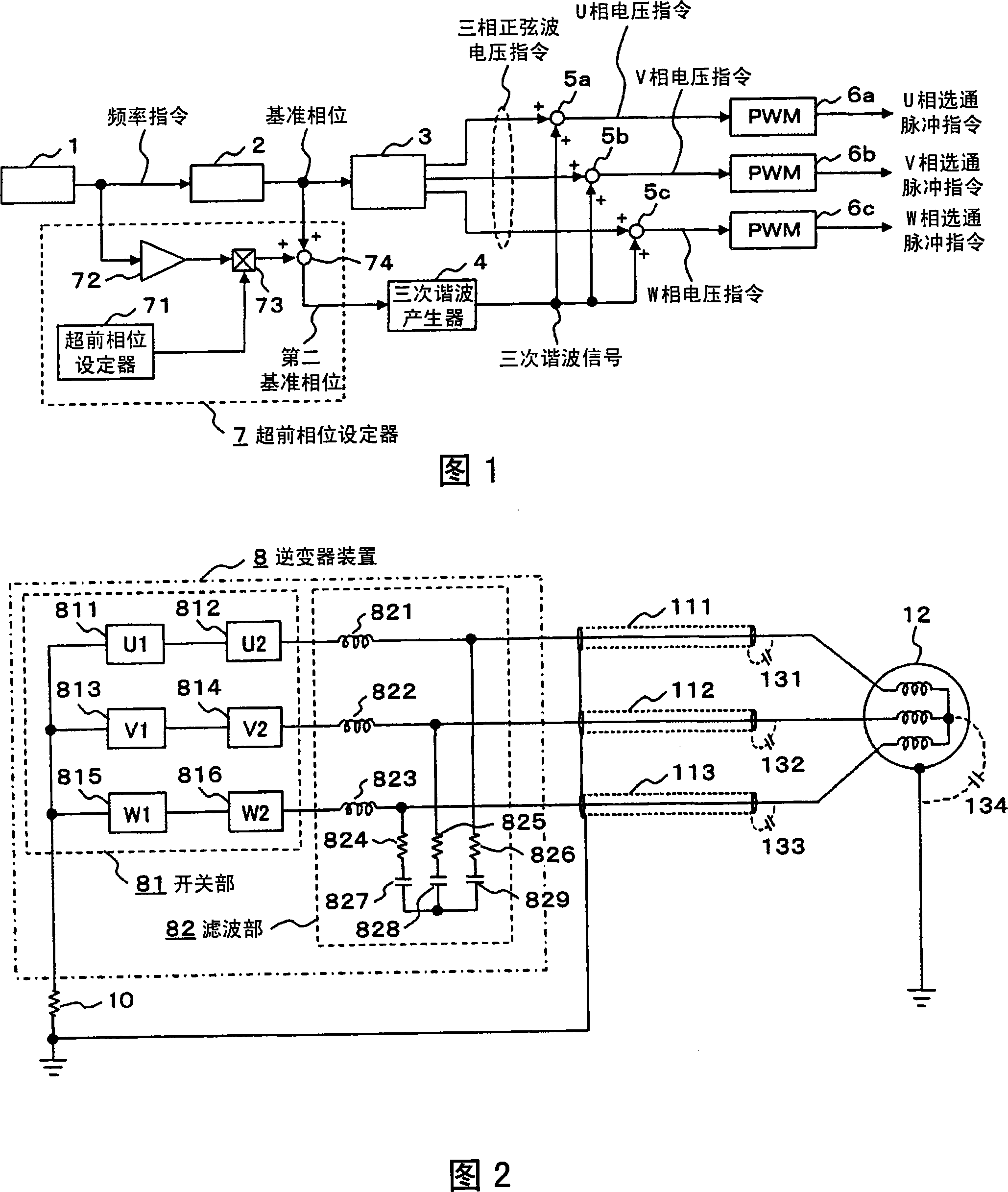
[0032] FIG. 1 is a functional block diagram of a control unit in a drive device for a three-phase AC motor according to an embodiment of the present invention.

[0033] In FIG. 1 , the reference phase calculator 2 receives the frequency command output from the frequency command device 1 to generate a reference phase signal, and the sine wave generator 3 generates a three-phase sine wave voltage command according to the reference phase signal.

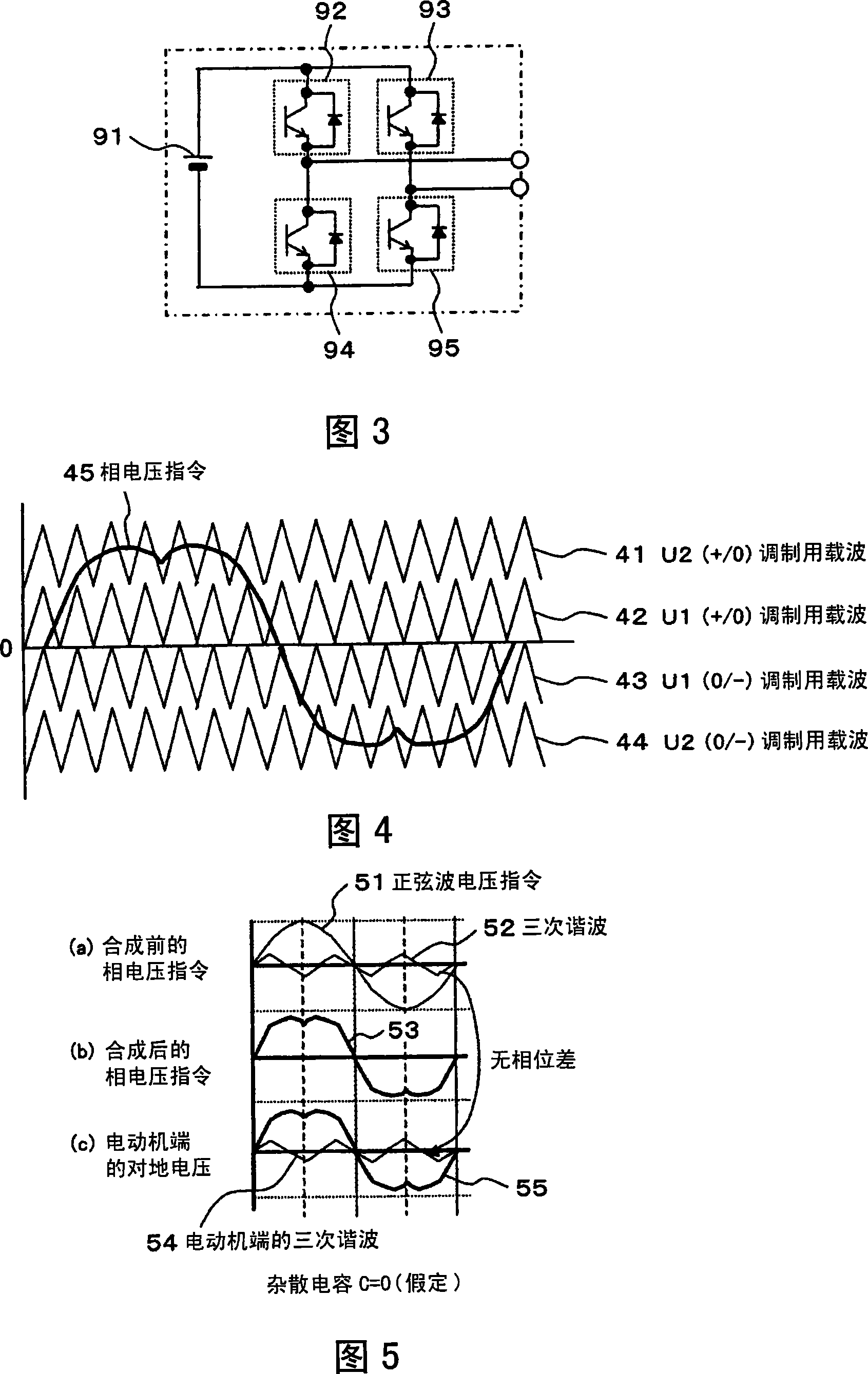
[0034] On the other hand, as for the third harmonic generator 4, first, starting from the basic operation disclosed in Patent Document 1, the voltage waveform is reduced to 1 / 2 times the magnitude by the three-phase sine wave of the same phase. Then output the third harmonic signal. Then, the voltage commands are synthesized by the adders 5a, 5b, and 5c, and are finally used as voltage commands for the U, V, and W phases of each phase.

[0035] These voltage commands are PWM-modulated by the PWM modulators 6a to 6c to become pulse comm...


PUM


Abstract

When a third harmonic (52) applied to an output voltage instruction (51) modulated by a PWM is showed in a motor (12) terminal, based on a resistance value (R) of an earthling resistor (10) of a main circuit of a phase inverter device (8), delayed earthling static capacitor (c) applying a wire (cable) of the power to the motor (12), applying the third harmonic (802) with the phase exceeding the retardation to a sine wave (51) of the output voltage instruction. Therefore, a control device that covers the large voltage power inverter by a same voltage resisting semiconductor switching element, in particular a control device of the power inverter for motor drive that reduces peak value of the voltage to ground of the motor terminal, lightens deterioration of the motor insulating material.

Description

technical field [0001] The invention relates to a control device and a control method of a three-phase power converter, and a drive device and a drive method of a three-phase AC motor. In particular, it relates to a control device, a control method, a drive device, and a drive method suitable for driving a three-phase AC motor through a grounded main circuit through a resistor and through an electric wire (cable) having an electrostatic capacitance to the ground. Background technique [0002] As disclosed in Non-Patent Document 1, the deterioration speed of the insulating material of the motor largely depends on the peak value of the voltage applied to the ground of the winding. [0003] Therefore, Patent Document 1 discloses a technique of reducing the voltage by adding and subtracting the third harmonic to the voltage command value (modulated wave) of each phase in order to make the fundamental wave component larger than the peak value of the output voltage. command peak....

Claims


Application Information

Patent Timeline
IPC IPC(8): H02M7/48H02P27/02H02P27/08H02P21/05H02P23/04H02P25/22H02P27/06
Inventor 冈松茂俊飞世正博
Owner HITACHI IND PROD LTD
Learn More