

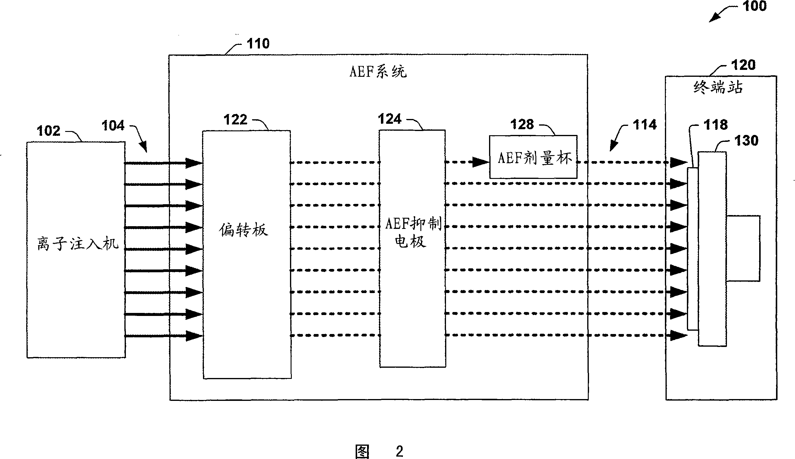
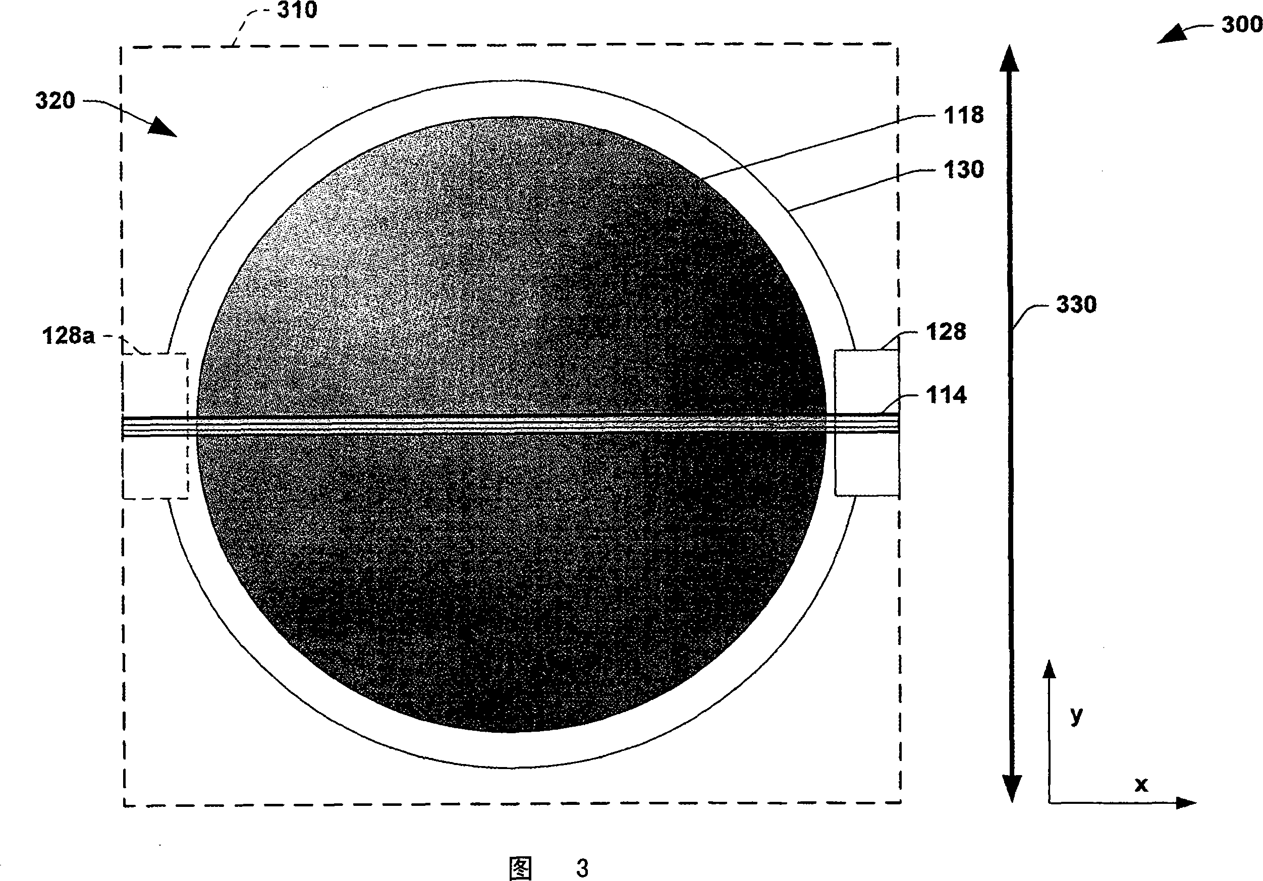
Dose cup located near bend in final energy filter of serial implanter for closed loop dose control
A technology of filters and dose cups, applied in circuits, discharge tubes, electrical components, etc., can solve problems such as correction or compensation of dose rate obstruction
- Summary
- Abstract
- Description
- Claims
- Application Information
AI Technical Summary
Problems solved by technology
Method used
Image

Examples
Embodiment Construction
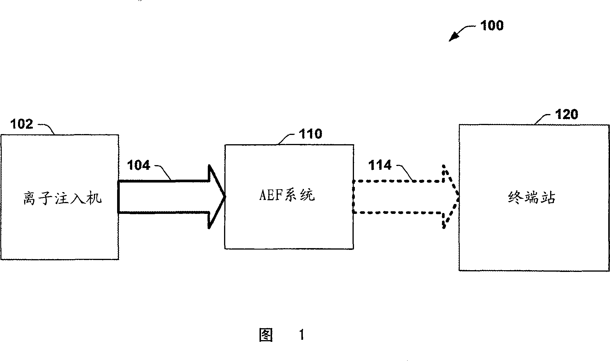
[0043] The invention will now be described with reference to the accompanying drawings, in which like reference characters indicate like parts throughout. The present invention provides a system and method for providing accurate ion current measurements correlated to the dose of a wafer for use with an ion implantation system. Such uses may include dosimetry, data logging, and feedback to the system for closed loop control of, for example, the speed of a wafer slow scan movement drive.
[0044] Dose control, especially in the presence of high pressure in the process chamber due to photoresist gas outgassing, requires a measure for determining the effective implant beam current when part of the ion beam is neutralized on its way to the wafer. This is traditionally achieved by measuring the pressure within the beam path and correcting the flow measured at the wafer in the end station by estimating the fraction that has become neutral based on the pressure and the known or empiri...
PUM
 Abstract
Description
Claims
Application Information