
Transport device in a facility for processing substrates

A technology for transporting devices and processing substrates, applied in the direction of transportation and packaging, conveyors, conveyor objects, etc., can solve problems such as interference sources, and achieve high-yield effects

Inactive Publication Date: 2008-08-13
APPLIED MATERIALS INC
View PDF1 Cites 3 Cited by
  • Summary
  • Abstract
  • Description
  • Claims
  • Application Information

AI Technical Summary

Problems solved by technology

Whether the transport involves belts, rails, or any other system, this transfer of substrates from one independent transport system to another is often associated with deviations in positioning accuracy, thus creating a permanent source of disturbance and error in the processing cycle
Furthermore, for unimpeded horizontal linear motion of the substrate, the structure of the transfer device must be designed to accommodate the transport device, which requires considerable space within the vacuum processing module

Method used


Image

  • Transport device in a facility for processing substrates
  • Transport device in a facility for processing substrates
  • Transport device in a facility for processing substrates

Examples


Embodiment Construction

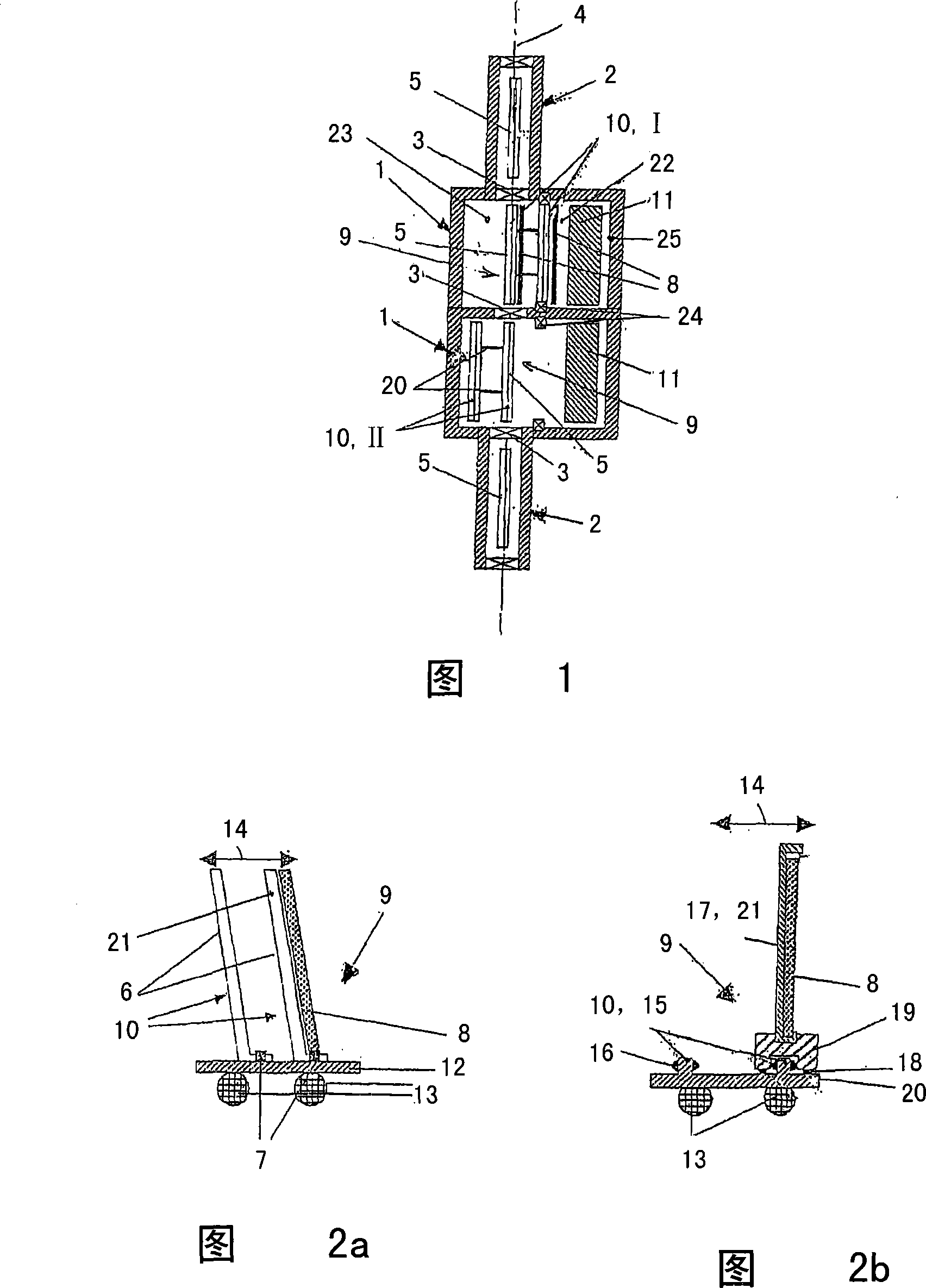
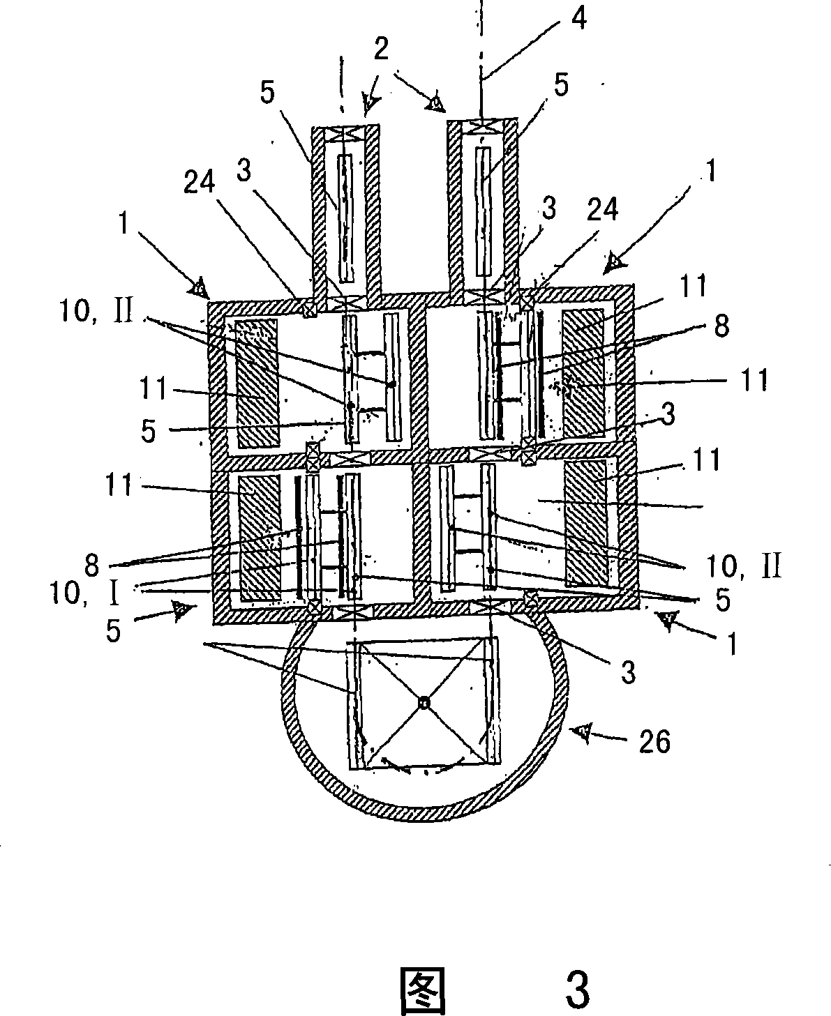
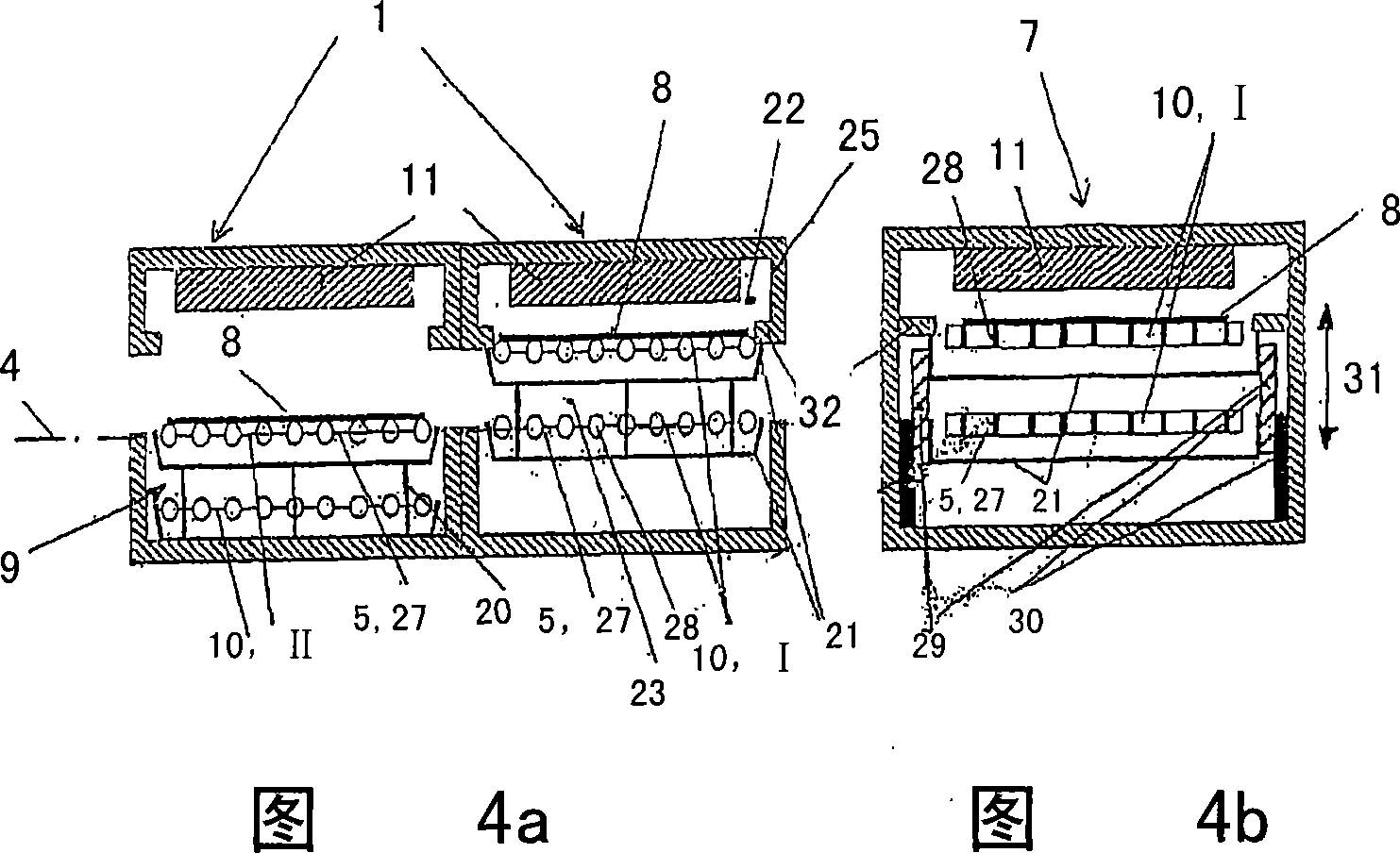
[0057] In FIG. 1, the vertical in-line coating apparatus according to embodiment A comprises two adjacent coating stations 1 and two adjacent lock chambers 2, wherein the coating stations 1 and the lock chambers 2 are controlled by a vacuum-tight chamber valve 3 to separate from each other. The transport device according to the invention passes through the lock chamber 2 and the coating station 1 , said device being formed by several transport segments 5 arranged in succession along the transport line 4 . The transport sections 5 according to embodiment A are formed for transporting substantially vertically aligned flat substrates 8, wherein, in particular, the transport sections 5 in FIG. Or substantially vertically oriented substrate guide plate 6, and transport rollers 7 are arranged at the base (can be easily seen from Fig. 2a), by means of transport rollers 7, a flat substrate 8 can stand slightly inclined along The transport line 4 transports through the in-line coating...


PUM


Abstract

Using a combi-segment (10), the substrate (8) can be positioned in a stationary treatment location. This places the substrate opposite the treatment tool (11). The combi-segments are arranged parallel to each other and spaced apart. They can be moved transversely, preferably at right angles to the transport line (4). They can be moved horizontally and / or vertically. The transfer unit (9) has a roller-, toothed wheel-, push- or pull drive. This is driven electrically, pneumatically or hydraulically. A transfer unit is provided in at least two successive treatment sections (1) or at least two successive treatment tools. It includes a chamber partition wall in a plane between combi-segments. The combi segment associated with the treatment tool and / or a substrate holder is constructed as a chamber partition wall. This wall has seals (24) corresponding with the chamber wall (25) of the treatment section. The transport segments are components of a roller, rail or gas cushion conveyor. The substrate treatment surface. This forms a transport plane during in-line transport of the substrate along the line (4). On positioning in the treatment location, the surface is located in a plane parallel to the transport plane. The treatment surface of the substrate is directed horizontally or vertically. The transport unit includes a rotation module with at least one transport segment (5) which can be allocated to the transport segments of two treatment sections. A plant employing the transport system is also claimed.

Description

technical field [0001] The invention relates to a transport device in a plant for processing substrates, which transport device has a continuous transport section for the continuous in-line transport of substrates along a transport line through several processing stations, wherein a device for A transfer device that positions each substrate to a fixed processing location. Background technique [0002] Such transport means can be found in plants for processing substrates in several successive processing stations, for example in vacuum coating plants for multilayer coatings such as special glass. These devices include an in-line arrangement, ie different coating stations in series, wherein the substrate is transported from one coating station to the next by means of a transport device. Corresponding to the structural sequence of the coating process in the coating station, various multilayer layer systems of different materials and thicknesses are applied by evaporation or spu...

Claims


Application Information

Patent Timeline
Patent Type & Authority Applications(China)
IPC IPC(8): C23C14/56
CPCC23C14/568B65G49/061B65G49/063B65G49/064B65G49/067B65G2249/02C23C16/54
Inventor W-E·弗里齐
Owner APPLIED MATERIALS INC
Learn More