Gear pump using water as pressure medium

A technology of hydraulic medium and application of water, applied in the field of hydraulic gear pump, can solve the problems of difficult processing and assembly, weak anti-pollution ability, short service life, etc., and achieve the effect of strong anti-pollution ability, low cost and long service life

Inactive Publication Date: 2008-08-27
HARBIN INST OF TECH
View PDF0 Cites 16 Cited by
  • Summary
  • Abstract
  • Description
  • Claims
  • Application Information

AI Technical Summary

Problems solved by technology

[0003] The purpose of the present invention is to solve the existing hydraulic plunger pumps with complex structure, difficult processing and assembly, high wear rate, high cost, low volum...

Method used


Image

  • Gear pump using water as pressure medium
  • Gear pump using water as pressure medium
  • Gear pump using water as pressure medium

Examples


specific Embodiment approach 1

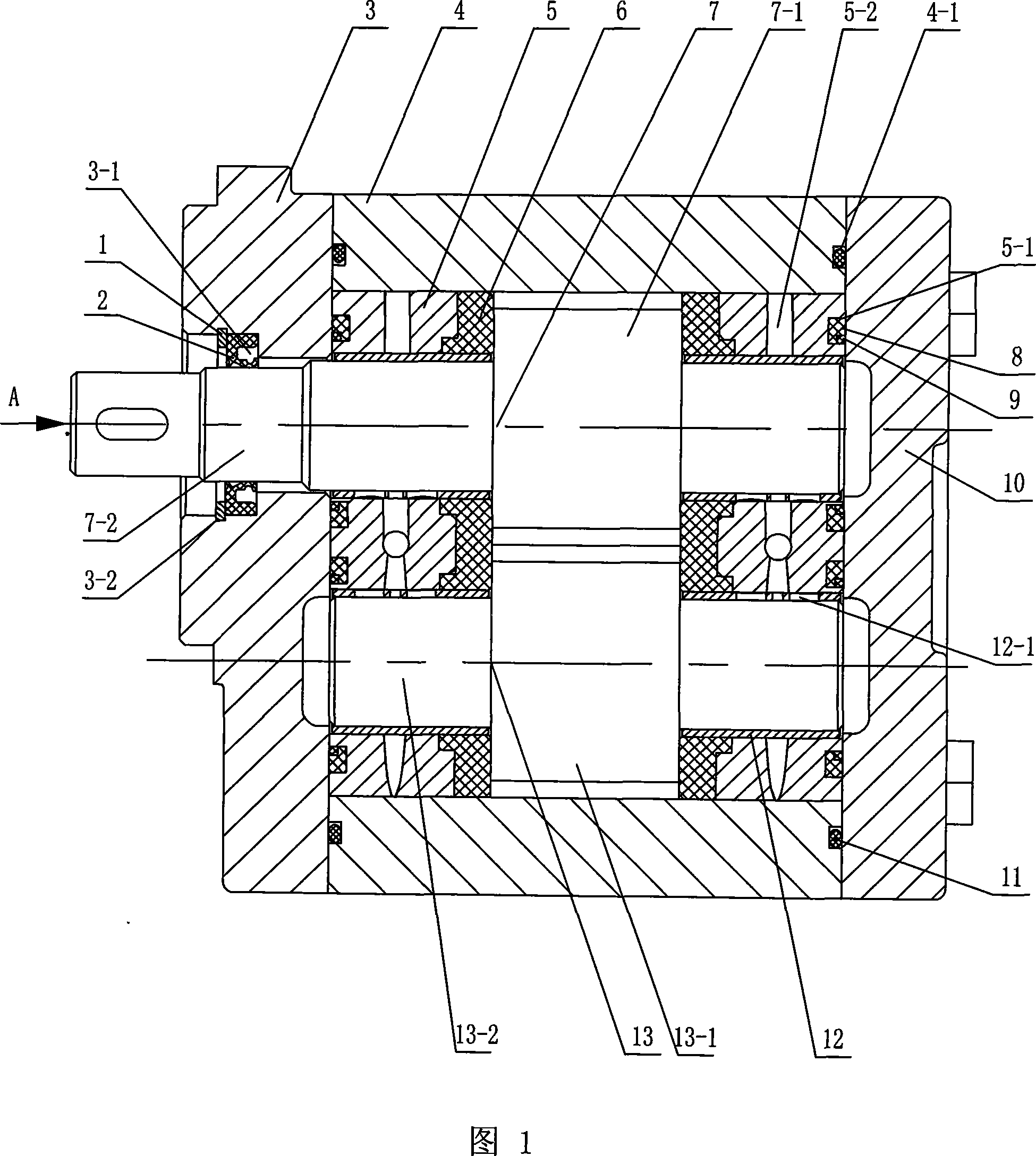
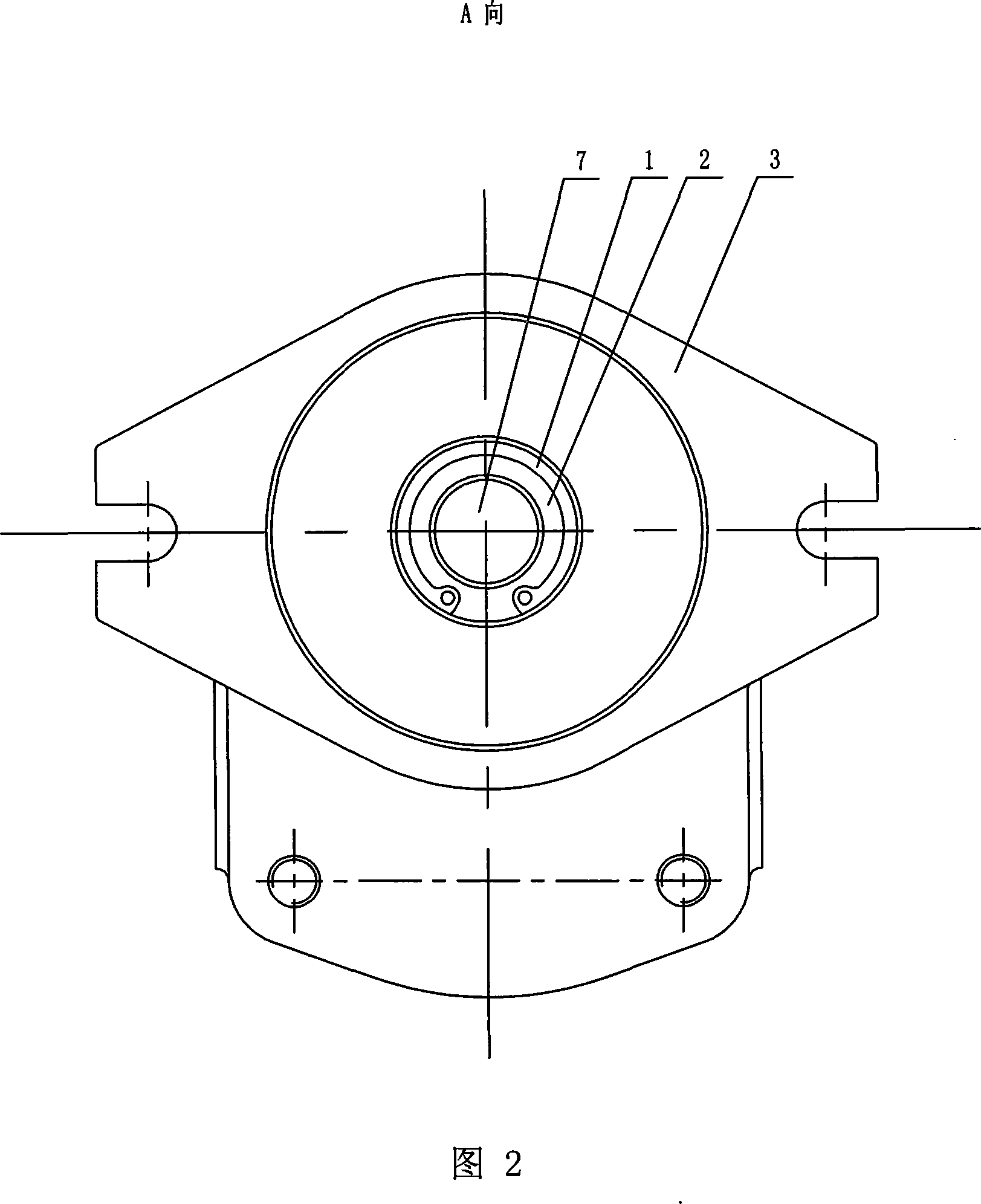
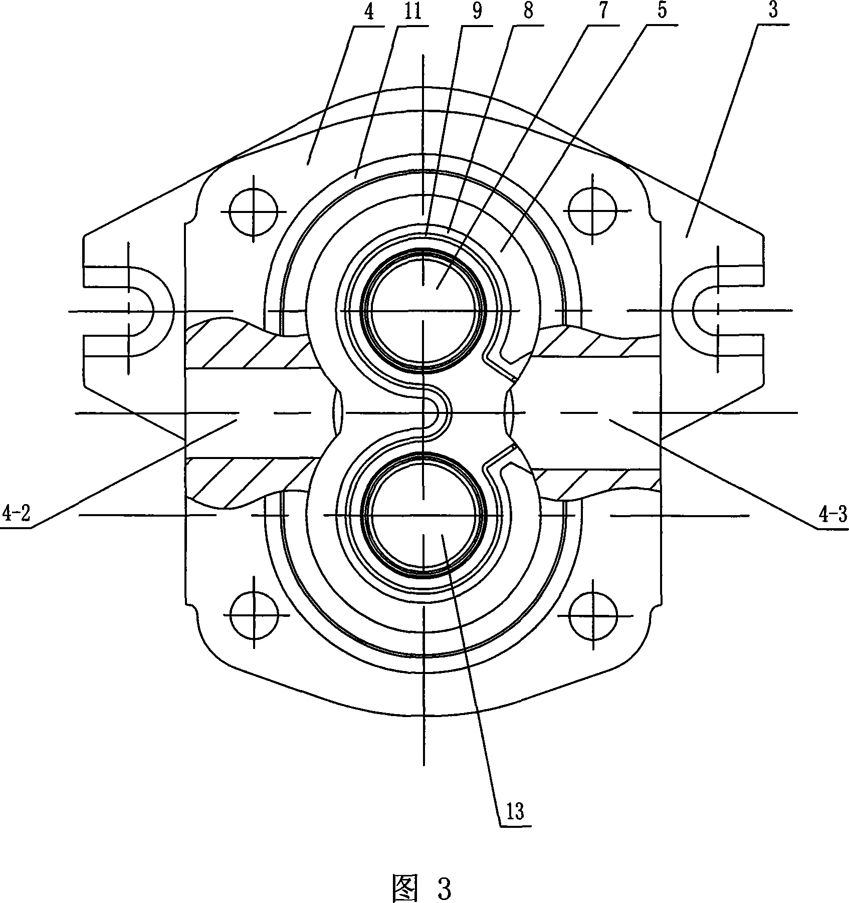
[0007] Specific embodiment 1: This embodiment is described in conjunction with Fig. 1 to Fig. 14. This embodiment consists of a spring retaining ring 1, a shaft sealing ring 2, a front end cover 3, a housing 4, a floating bushing 5, a side plate 6, and a driving gear Shaft 7, floating sleeve sealing ring 8, sealing ring bracket 9, rear end cover 10, housing sealing ring 11, sliding bearing 12 and driven gear shaft 13, the front end face of the housing 4 is equipped with a front end cover 3. A rear end cover 10 is installed on the rear end surface of the housing 4, and an annular groove 4-1 is respectively opened on the joint surface of the housing 4, the front end cover 3 and the rear end cover 10, and the sealing ring of the housing 11 is installed in the annular groove 4-1, and the left and right side walls of the housing 4 are respectively provided with a water inlet hole 4-2 and a water outlet hole 4-3, and the shoulder hole 3-1 of the front end cover 3 A shaft sealing rin...

specific Embodiment approach 2

[0008] Specific Embodiment 2: This embodiment is described with reference to FIG. 1 . In this embodiment, a hydraulic radial force balance hole 5-2 is opened on the floating bushing 5 . Such a setting can make the radial force tend to be in a balanced state. Other compositions and connections are the same as in the first embodiment.

specific Embodiment approach 3

[0009] Specific Embodiment 3: This embodiment is described with reference to FIG. 1 and FIG. 13 . The sliding bearing 12 of this embodiment is provided with a lubricating hole 12 - 1 . Such setting increases the lubrication of the sliding bearing. Other compositions and connections are the same as in the first embodiment.


PUM


Abstract

A gear pump adopting water as hydraulic medium relates to a hydraulic gear pump. The invention solves the problems of the prior hydraulic pressure plunger pump such as a complex structure, difficult processing and assembling, high wear rate, high cost, low floor area ratio, short service life and poor antipollution capacity and is only suitable to be used under high-pressure conditions. The invention adopts the following structure: the front sides and the back sides of a driving gear (7-1) of a driving gear shaft (7) and a driven gear (13-1) of a driven gear shaft (13) are provided with side plates (6); the end faces of the side plates (6) with the back towards the driving gear (7-1) and the driven gear (13-1) are provided with floating shaft sleeves (5); sliding bearings (12) are respectively arranged among the floating shaft sleeves (5), the side plates (6) and the driving shaft (7-2) of the driving gear shaft (7), as well as among the floating shaft sleeves (5), the side plates (6) and a driven shaft (13-2) of the driven gear shaft (13). The development of the gear pump is the complement of a hydraulic pressure element and is of great significance to speed up the development of the hydraulic pressure transmission technical field, enlarge the application scope of hydraulic pressure transmission and realize the technology which replaces oil pressure transmission by hydraulic pressure transmission.

Description

technical field [0001] The invention relates to a hydraulic gear pump, belonging to the technical field of fluid transmission devices. Background technique [0002] Pure water hydraulic transmission not only has the characteristics of large transmission power, high efficiency, small size and light weight of oil hydraulic transmission, but also has the advantages of high safety, environmental friendliness, saving oil resources and wide application range. However, the existing hydraulic plunger pumps have problems such as complex structure, difficult processing and assembly, high wear rate, high cost, low volumetric efficiency, short service life, weak anti-pollution ability and only suitable for high-pressure applications. Contents of the invention [0003] The purpose of the present invention is to solve the existing hydraulic plunger pumps with complex structure, difficult processing and assembly, high wear rate, high cost, low volumetric efficiency, short service life, w...

Claims


Application Information

Patent Timeline
IPC IPC(8): F04C2/14F04C15/00
Inventor 姜继海王强
Owner HARBIN INST OF TECH
Why Eureka
Try Eureka