Photon crystal optical fiber fusion splicing three-dimensional alignment apparatus and method

A technology of photonic crystal fiber and alignment device, which is applied in the coupling of optical waveguide, program control in sequence/logic controller, electrical program control, etc. Hole alignment, the inability to achieve complete alignment of the fused fiber core, etc., to achieve the effect of simple structure, strong anti-vibration interference ability, and high sensitivity

Inactive Publication Date: 2008-08-27
YANSHAN UNIV
View PDF0 Cites 12 Cited by
  • Summary
  • Abstract
  • Description
  • Claims
  • Application Information

AI Technical Summary

Problems solved by technology

[0003] The existing ordinary optical fiber fusion splicers and polarization-maintaining optical fiber fusion splicers cannot automatically complete the three-dimensional alignment of photonic crystal fibers with high quality. It uses the different extinction ratios of the polarization-maintaining fiber core defects in different directions, and achieves alignment through the maximum coincidence degree of the POL (Polarization Observation by Lens-effect-tracing) curve. However, if the photonic crys...

Method used


Image

  • Photon crystal optical fiber fusion splicing three-dimensional alignment apparatus and method
  • Photon crystal optical fiber fusion splicing three-dimensional alignment apparatus and method
  • Photon crystal optical fiber fusion splicing three-dimensional alignment apparatus and method

Examples


Embodiment

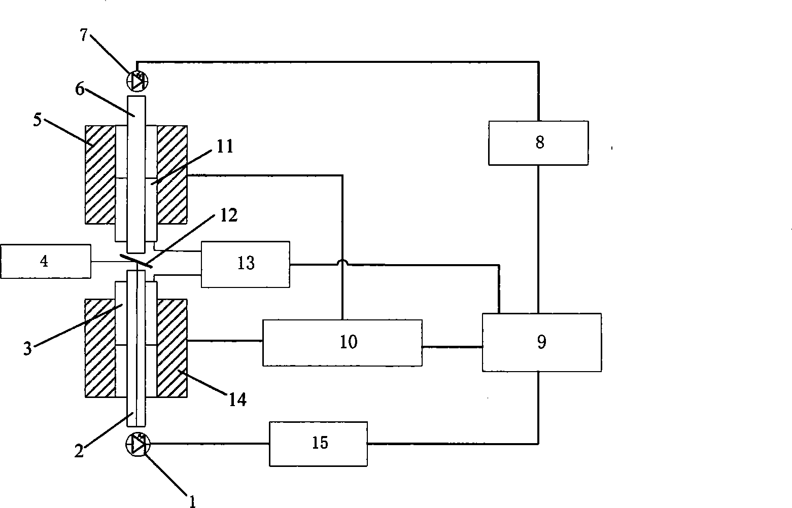
[0020] In this embodiment, the upper photonic crystal fiber 6 and the lower photonic crystal fiber 2 that are fused and aligned are photonic crystal fibers of the same specifications, and the fiber specifications are: mode field radius 7.5 μm, fiber core diameter 10.9 μm, hole spacing 3 μm, air hole diameter 2μm, 6 air hole layers.

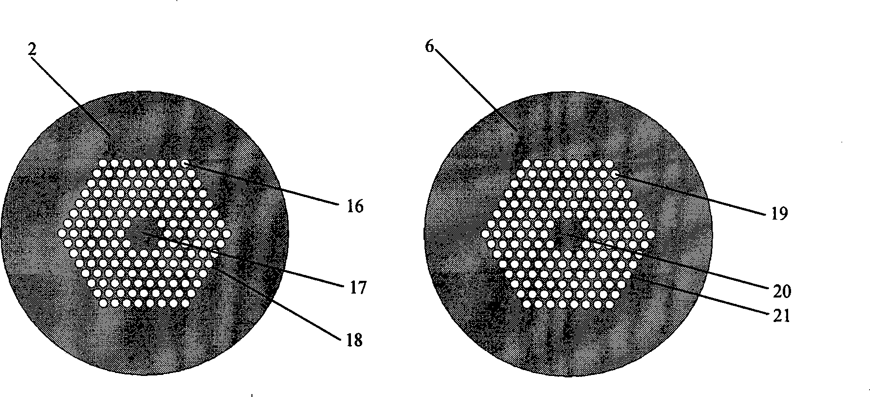
[0021] a. First use the microscopic imaging unit 4 to obtain the structural information of the end face of the fused photonic crystal fiber, such as figure 2 shown. Then use the Hough transform to identify and locate the geometric structure of the photonic crystal fiber end face, determine the center of the core (17, 20), the center of each air hole in the cladding (16, 19) and the outer diameter (18, 21), and then determine the cladding For the arrangement of air holes in the layer, coordinate positioning is carried out by using software algorithms.

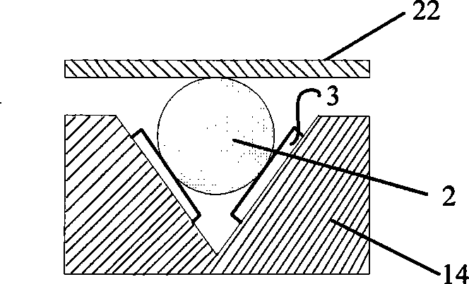
[0022] b. The upper and lower three-dimensional motion V-groove devices (5, 14) pass the lowe...


PUM


Abstract

The invention discloses a three-dimensional alignment device for welding a photonic crystal fiber and a method thereof, wherein, mechanical transmission mechanisms of an upper three-dimensional motion V-shaped groove device (5) and a lower three-dimensional motion V-shaped groove device (14) of the device are connected with an alignment controller of a three-dimensional alignment controller and a clamp control unit (10), and a lower stress sensor (3) and an upper stress sensor (11) are connected with a stress sensor modulating unit (13); a double-sided holophote (12) of a micro-imaging unit (4) images a head face of the photonic crystal fiber and captures a geometric structure of the photonic crystal fiber which is positioned and identified by using a Hough transformation; and light emission and light receiving are achieved by coupling type light intensity determination units (1, 7, 8 and 15). The method comprises the following steps that: 1) the micro-imaging unit (4) acquires information of structure, and performs an identification and position for the geometric structure of the photonic crystal fiber by using the Hough transformation; 2) a clamping force is automatically adjusted by the upper three-dimensional motion V-shaped groove device (5) and the lower three-dimensional motion V-shaped groove device (14); 3) an initial alignment is performed for the photonic crystal fiber; and then a fine alignment is performed for the photonic crystal fiber. The three-dimensional alignment device for welding a photonic crystal fiber has the advantages of simple structure, strong capability of anti-interference of vibration and high sensitivity, and is suitable for the three-dimensional alignment between the photonic crystal fibers with different specifications and between the photonic crystal fiber and a conventional optical fiber.

Description

Technical field: [0001] The invention relates to the technical field of photonic crystal fiber fusion, in particular to a photonic crystal fiber fusion three-dimensional alignment device and method thereof. Background technique [0002] Photonic crystal fiber came out in the UK in 1996. This kind of fiber has many singular characteristics that ordinary fibers do not have, such as high nonlinearity, controllable dispersion, high birefringence, infinite single-mode characteristics, etc., and can be widely used in In the fields of communication, imaging, spectroscopy and biomedicine, its performance research and application development have always been a hot spot in the international optoelectronics industry. However, the photonic crystal fiber fusion splicing technology is still immature and still in the exploratory research stage, and has become a practical problem that must be solved in the application and development of photonic crystal fiber. The first problem that must b...

Claims


Application Information

Patent Timeline
IPC IPC(8): G02B6/255G05B19/04
Inventor 毕卫红付广伟麻硕
Owner YANSHAN UNIV
Why Eureka
Try Eureka