
LED three-dimensional optical system design method and optical system with given luminous intensity distribution

A technology of illuminance distribution and three-dimensional optics, which is applied in the field of non-imaging optics, and can solve the problems that the refraction scheme is not easy to fully utilize the energy of the light source, increases the cost, and cannot guarantee the uniformity of illuminance.

Active Publication Date: 2008-08-27
TSINGHUA UNIV
View PDF0 Cites 22 Cited by
  • Summary
  • Abstract
  • Description
  • Claims
  • Application Information

AI Technical Summary

Problems solved by technology

In the design scheme that only uses refraction, the change degree of the exit angle of the light source light is limited. When realizing an optical system with a small exit angle, the light source light with a large angle cannot guarantee the existence of a refraction surface, that is, for the small exit angle requirements Large-angle light source light cannot be considered in the design of the light source, thereby reducing the light energy utilization rate of the light source. For example, in the design of street lights, the width of the road limits the size of the lateral light angle, and the refraction scheme is not easy to make full use of the light source energy on the horizontal scale.
However, the design scheme using total internal reflection is easy to achieve uniform illuminance in a small angle, but cannot ensure the uniformity of illuminance at a large exit angle, which forces the designer to increase the distance between the system and the target area to reduce the light exit angle, such as In the design of street lamps, the height is increased to reduce the light exit angle, thereby increasing the cost in disguise; in addition, compared with refraction, the angle error of the light source light after total internal reflection will be doubled, which also increases the requirements for manufacturing accuracy

Method used


Image

  • LED three-dimensional optical system design method and optical system with given luminous intensity distribution
  • LED three-dimensional optical system design method and optical system with given luminous intensity distribution
  • LED three-dimensional optical system design method and optical system with given luminous intensity distribution

Examples


Embodiment Construction

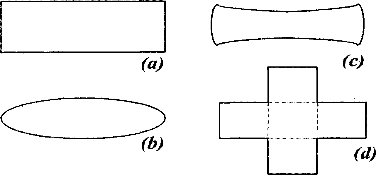
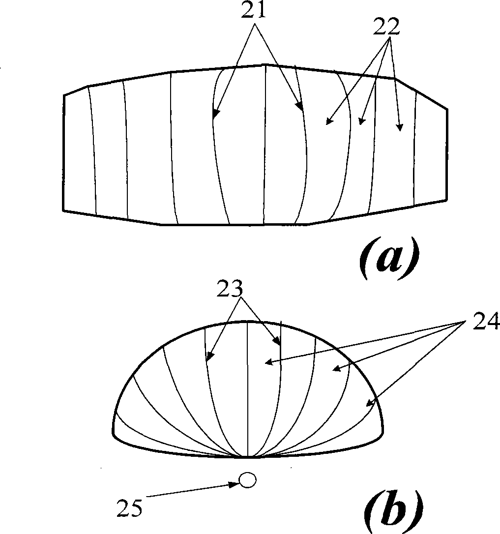
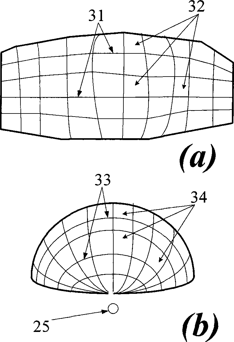
[0049] As a new type of lighting source, LED is small in size and can be approximately regarded as a point light source in the package lens design. The lens design method proposed in the present invention is based on the principle of energy conservation, divides the energy of the illuminance plane and the energy of the point light source according to the plane coordinates and direction angles, and makes the energy one-to-one correspondence. In this division process, the algorithm in the present invention firstly separates the energy of the illuminance plane according to the major axis and the minor axis, and at the same time separates the energy of the light source according to the corresponding directions, and calculates the corresponding relationship of energy in the two axial directions; then Establish respective discrete points in the coordinates of the illuminance plane and the coordinates of the angle direction of the light source and correspond them one by one; then, acc...


PUM


Abstract

The present invention discloses an LED three-dimensional optical system design method with given illumination distribution and an optical system, which belongs to the non-imaging optical technique of the applied optics field. A three-dimensional non-imaging optical system is formed in a region which has given illumination distribution, by using a light emitting diode as a light source. A three-dimensional lens is designed with the optical system. According to the geometrical shape of the given illumination distribution region, complying with the law of conversation of energy, the surface of the light source and the illumination plane are divided into corresponding energy regions on the long axis direction of the region in accordance with optical refraction, and energy division is carried out in the short axis direction in accordance with the principle of common function of total internal reflection and refraction. The coordinates and the normal vectors of all feature points of the optical system surface of the light source along the long axis direction and the short axis direction are calculated according to the energy corresponding relationship, so as to determine the optical system surface. The method and the system contribute to sufficiently utilizing energy and reducing engineering cost. The encapsulation of the optical system is flexible. Single chip encapsulation and multi-chip encapsulation can be adopted. The arrangement of a plurality of the optical systems is free, simple and flexible.

Description

technical field [0001] The invention belongs to the non-imaging optical technology in the field of applied optics, and in particular relates to a design method and an optical system of an LED three-dimensional optical system with a given illuminance distribution using light emitting diodes (LEDs) as a light source based on the non-imaging optical technology. Background technique [0002] Compared with traditional light sources, LED is an all-solid-state light source, which has many advantages such as energy saving, environmental protection, rich colors, small size, compact structure, fast response, shock resistance, and impact resistance. Lamps, mine lighting, field operations and military operations and many other fields have become the third-generation lighting sources that have attracted much attention. The LED light source is small in size, and its light intensity distribution attenuates rapidly with the increase of the output angle, which can be approximately regarded a...

Claims


Application Information

Patent Timeline
IPC IPC(8): G02B27/00
Inventor 罗毅张贤鹏韩彦军钱可元
Owner TSINGHUA UNIV
Learn More