Energy-saving type sodium sulphite circulation desulfurizing device and method

A technology of sodium sulfite and desulfurization device, applied in the field of flue gas desulfurization, can solve the problem of insufficient utilization of flue gas waste heat, and achieve the effects of being beneficial to environmental protection, reducing operating costs, and ensuring process flow

Inactive Publication Date: 2008-09-03
向瑞先
View PDF2 Cites 19 Cited by
  • Summary
  • Abstract
  • Description
  • Claims
  • Application Information

AI Technical Summary

Problems solved by technology

In addition, the utilization of the waste heat of the flue gas is not sufficient

Method used


Image

  • Energy-saving type sodium sulphite circulation desulfurizing device and method

Examples


Embodiment 1

[0039] Embodiment 1: Sodium carbonate is used as the initial absorbent, and the flue gas is desulfurized by an energy-saving sodium sulfite circulating desulfurization device.

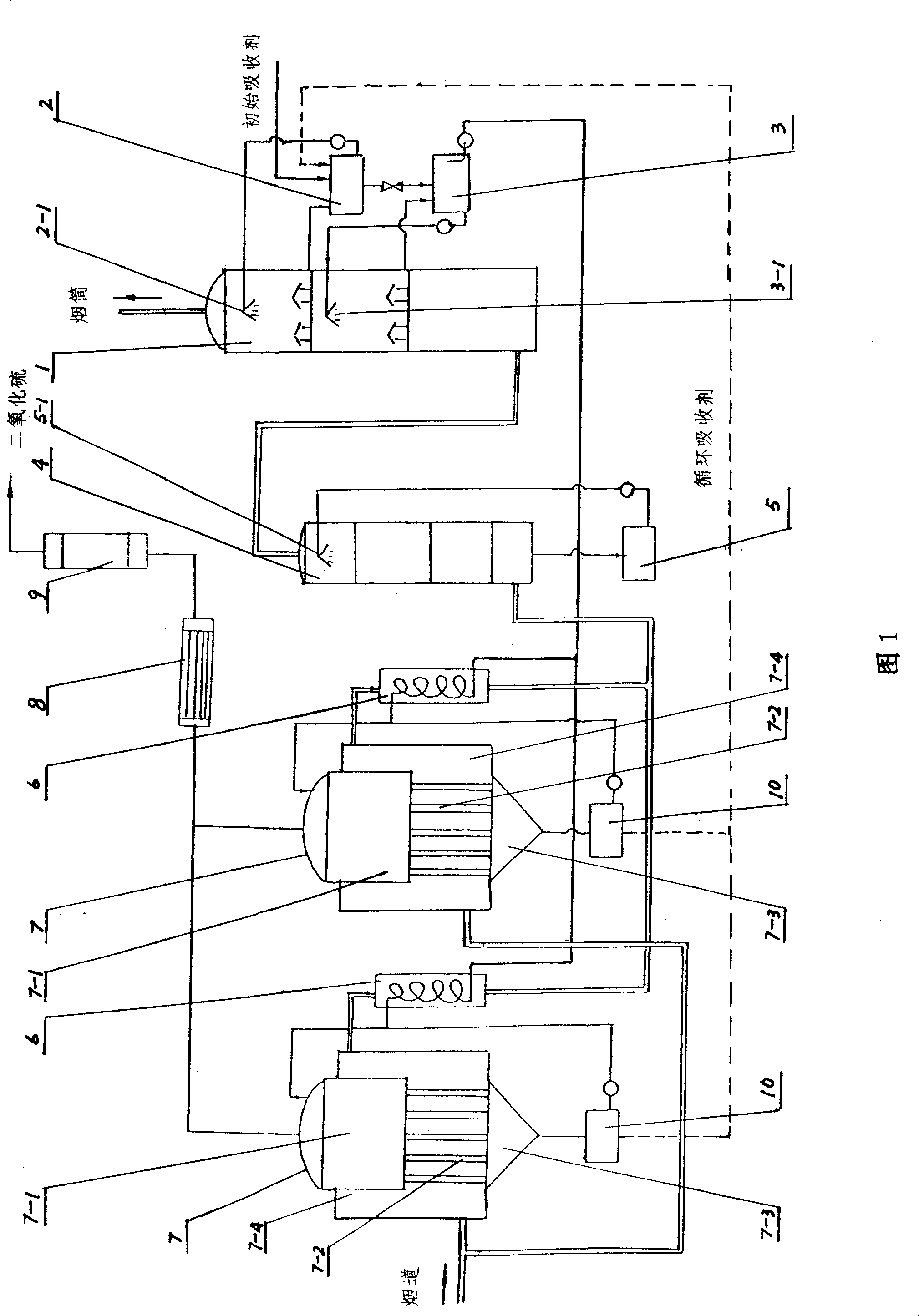
[0040] Referring to Figure 1, the interior of the desulfurization tower 1 of the energy-saving sodium sulfite circulating desulfurization device is divided into upper, middle and lower areas by two intervals, and the first absorption liquid circulation tank 2 and the second absorption liquid circulation tank 3 are located in the desulfurization tower outside, the bottom of the upper area of ​​the desulfurization tower communicates with the first absorption liquid circulation tank, the bottom of the middle area of ​​the desulfurization tower communicates with the second absorption liquid circulation tank, and the bottom of the first absorption liquid circulation tank communicates with the second absorption liquid circulation tank; The first nozzle 2-1 connected to the first absorption liquid circulation ...

Embodiment 2

[0059]Embodiment 2: Sodium carbonate is used as the initial absorbent, and the flue gas is desulfurized by an energy-saving sodium sulfite circulating desulfurization device.

[0060] The first step is to prepare the initial absorption solution: the initial absorption agent is Na 2 CO 3 , add soft water (deionized water) into the first absorption liquid circulation tank 2, and gradually add Na 2 CO 3 , so that the concentration by weight in the solution is 16%. After fully dissolving, add 0.05% of the solution weight antioxidant-p-phenylenediamine, and stir evenly; the rest of the steps are the same as in Example 1.

Embodiment 3

[0061] Embodiment 3: Sodium carbonate is used as the initial absorbent, and the flue gas is desulfurized by an energy-saving sodium sulfite circulating desulfurization device.

[0062] The first step is to prepare the initial absorption solution: the initial absorption agent is Na 2 CO 3 , add soft water (deionized water) into the first absorption liquid circulation tank 2, and gradually add Na 2 CO 3 , so that the concentration by weight in the solution is 18%. After fully dissolving, add 0.05% antioxidant-hydroquinone by solution weight and stir evenly; the rest of the steps are the same as in Example 1.


PUM


Abstract

The invention relates to an energy-saving sodium sulfite circulation and desulfurization device as well as the method thereof, the desulfurization device comprises a desulfurization tower as well as a first and a second absorption liquid circulation grooves, the top part of the desulfurization tower is communicated with a chimney, the lower part of the desulfurization tower is communicated with the top part of a washing and cooling tower, and the bottom part of the washing and cooling tower is communicated with a circulation washing groove. The invention is characterized in that the washing and cooling tower is communicated with a heat exchanger, which is then communicated with a flue after being communicated with a decomposed jacket reactor; the second absorption liquid circulation groove is communicated with a coil pipe in the heat exchanger, and the coil pipe is communicated with the reaction chamber of the decomposed jacket reactor; the lower part of the decomposed jacket reactor is communicated with a centrifuge. The invention has the desulfurization steps as follows: initial absorption liquid is prepared, the temperature of smoke is reduced, sulfur dioxide is absorbed, sodium bisulfite is decomposed, and sodium sulfite is recycled. The waste heat of the smoke is fully utilized, initial absorber is changed into circulation absorber to be used, the running cost is reduced, and the environment protection is favored.

Description

technical field [0001] The invention relates to a flue gas desulfurization method, in particular to an energy-saving sodium sulfite circulating desulfurization device and method. Background technique [0002] In my country, coal combustion accounts for more than 70% of the primary energy. Since coal contains sulfur, a large amount of SO is produced after combustion. 2 , resulting in serious air pollution. Therefore, the task of flue gas desulfurization is very heavy. At present, desulfurization of flue gas is the most important way to reduce SO 2 The most effective method for emissions and acid rain formation, the wet flue gas desulfurization technology that has been successfully operated has an absolute advantage with the calcium method. The calcium method uses calcium carbonate (ie limestone) as the absorbent, and its chemical reaction is as follows: [0003] CaCO 3 +SO 2 +1 / 2H 2 O=CaSO 3 1 / 2H 2 O+CO 2 ↑ [0004] 2CaSO 3 1 / 2H 2 O+3H 2 O=2CaSO 4 2H 2 o [0...

Claims


Application Information

Patent Timeline
Patent Type & Authority Applications(China)
IPC IPC(8): B01D53/50B01D53/78
Inventor 向瑞先向江涛向海燕
Owner 向瑞先
Why Eureka
Try Eureka