
2-dimensional marking device and marking method for digital aviation measuring camera

A technology for aerial survey cameras and calibration devices, which is applied in image data processing, instruments, calculations, etc., and can solve the problems that the distortion measurement of the whole camera is not applicable, and the measurement device of the collimator group method is complicated and unsuitable.

Inactive Publication Date: 2008-09-10
INST OF OPTICS & ELECTRONICS - CHINESE ACAD OF SCI
View PDF0 Cites 25 Cited by
  • Summary
  • Abstract
  • Description
  • Claims
  • Application Information

AI Technical Summary

Problems solved by technology

[0003] Most of the current indoor calibration methods for aerial survey cameras are purely optical calibration methods, including: forward / reverse node slide rail method, collimator group method and angle measurement method, among which the forward / reverse node slide rail method is not suitable for the whole camera distortion measurement; the measuring device of the collimator group method is complex; the traditional angle measurement method is suitable for film-type aerial survey cameras, and is not suitable for the calibration of large-field-of-view and large-area digital aerial survey cameras.

Method used

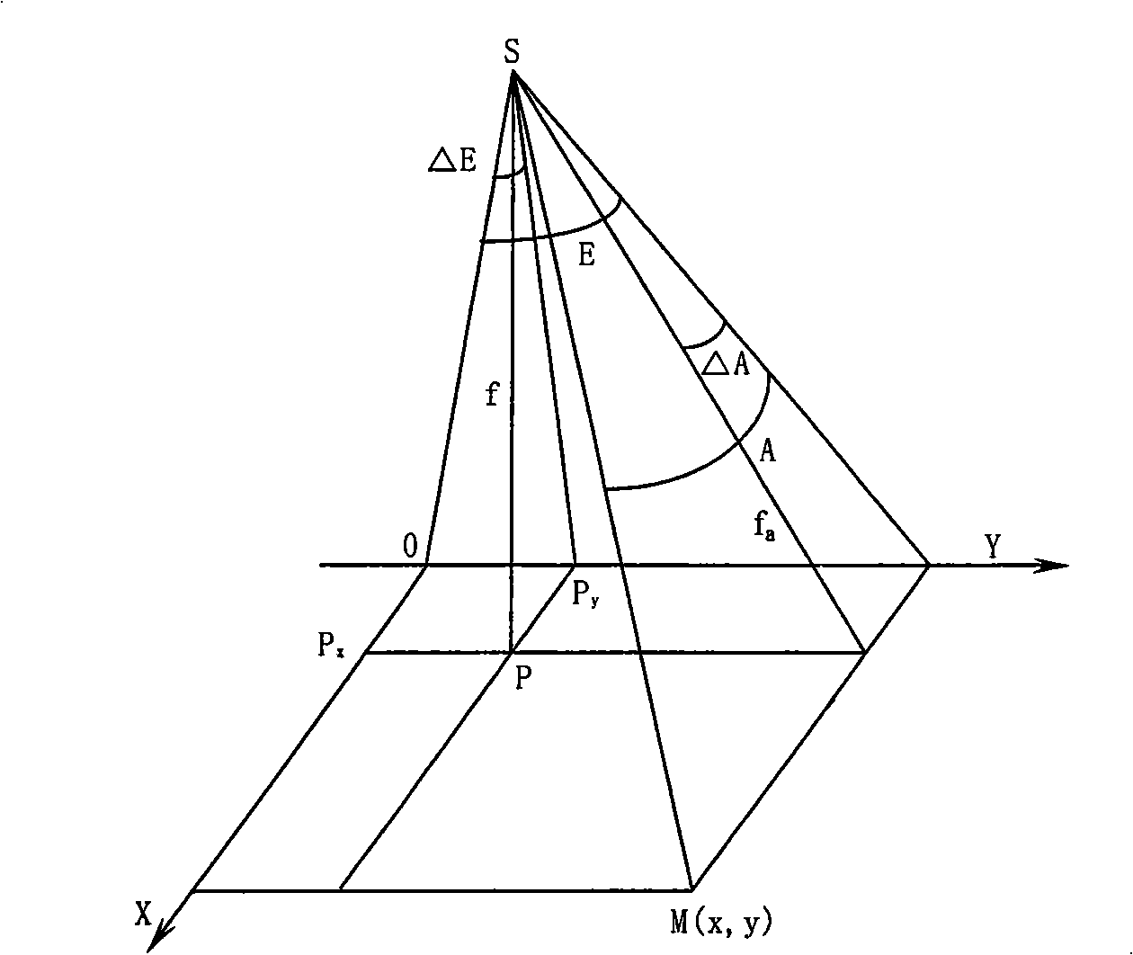
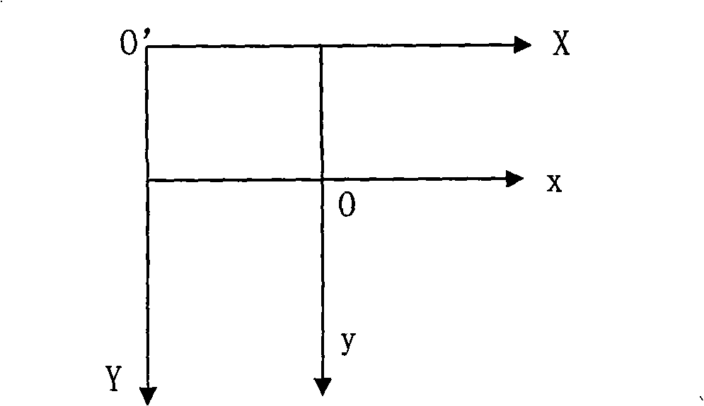

Image

  • 2-dimensional marking device and marking method for digital aviation measuring camera
  • 2-dimensional marking device and marking method for digital aviation measuring camera
  • 2-dimensional marking device and marking method for digital aviation measuring camera

Examples


Embodiment Construction

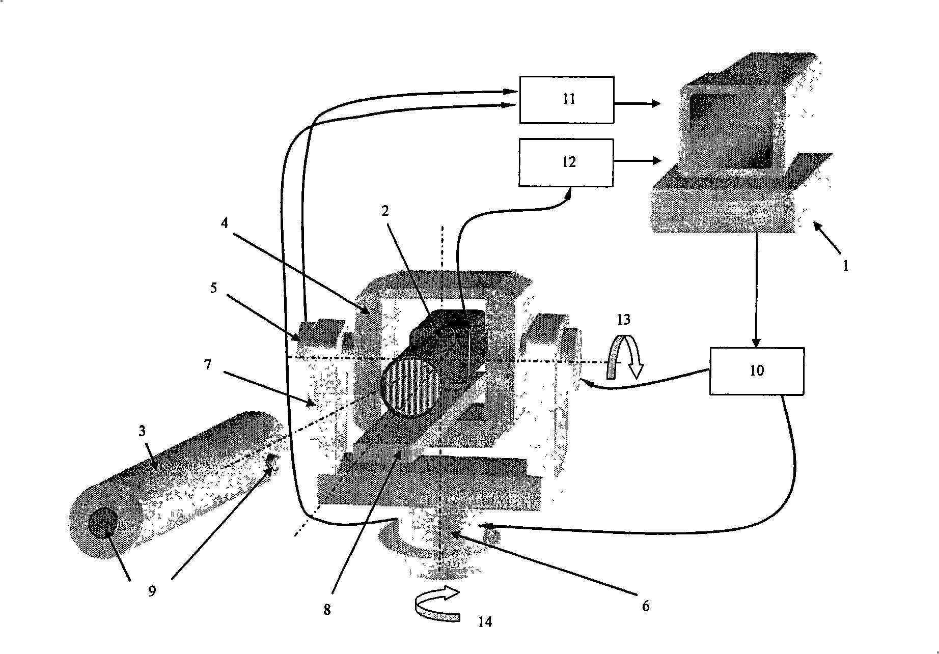
[0027] Such as figure 1 As shown, the present invention is mainly composed of an inner azimuth, a computer 1, a measured aerial survey camera 2 and a collimator 3. The internal azimuth instrument is mainly composed of the fixed frame 4 of the system under test, the pitch axis 5, the azimuth axis 6 and the two-axis turntable 7. The two-axis turntable 7 is designed with a high-precision encoder inside, and the fixed frame 4 of the system under test is connected with the pitch axis 5. It can rotate synchronously with the pitch axis 5, and the two-axis turntable 7 is closely connected with the azimuth axis 6 in addition to being connected with the pitch axis 5. The rotation of the azimuth axis 6 can drive the two-axis turntable 7 and the pitch axis 5 to rotate in the horizontal direction at the same time; The measurement direction range 13 of the pitch angle of the azimuth is ±35°, and the measurement direction range 14 of the azimuth angle is ±45°. The aerial survey camera 2 und...


PUM


Abstract

The invention relates to a two dimensional calibrating device of a digital aerial survey camera and a calibrating method thereof; the two dimensional calibrating device consists of an internal azimuth instrument, a computer, the aerial survey camera to be detected and a collimated light tube; the internal azimuth instrument is a two dimensional fine internal azimuth instrument and mainly includes a fixing frame of a detected system, a pitch axis, an azimuth axis and two axle tables; the aerial survey camera to be detected is arranged in the fixing frame of the detected system of the internal azimuth instrument; the collimated light tube is arranged in front of the aerial survey camera to be detected; in the calibrating process, the computer controls the rotation of the pitch axis and the azimuth axis of the internal azimuth instrument by driving a controlling device; collects the data outputted by the coders arranged in the pitch axis and the azimuth axis; carries out image point location collection on the aerial survey camera to be detected through an image collecting card; the computer calibrates the internal orientation elements and aberrances in the aerial survey camera to be detected by utilizing the collected angle values of the pitch and the azimuth coders and the pixel coordinate of the corresponding image point and through a mathematical model. The two dimensional calibrating device of the digital aerial survey camera and the calibrating method thereof of the invention realizes the accurate calibrating of the digital aerial survey camera with large field coverage and large area array; moreover, the calibrating device is simple and has high calibrating precision.

Description

technical field [0001] The invention relates to a two-dimensional calibration device of a digital aerial survey camera and a calibration method thereof. Background technique [0002] In order to improve the measurement accuracy of aerial survey cameras, usually before each aerial survey camera performs aerial photography tasks, strict calibration is required to measure the internal orientation elements and distortion of aerial survey cameras. [0003] Most of the current indoor calibration methods for aerial survey cameras are purely optical calibration methods, including: forward / reverse node slide rail method, collimator group method and angle measurement method, among which the forward / reverse node slide rail method is not suitable for the whole camera distortion measurement; the measuring device of the collimator group method is complicated; the traditional angle measurement method is suitable for film aerial survey cameras, but not suitable for the calibration of large ...

Claims


Application Information

Patent Timeline
IPC IPC(8): G06T7/00
Inventor 黄静马文礼高晓东梁伟
Owner INST OF OPTICS & ELECTRONICS - CHINESE ACAD OF SCI
Learn More