Blast furnace top dust-collecting equipment

A technology of dust removal device and blast furnace, which is applied in the direction of dust collector, etc., can solve the problems of high recycling cost, easy dust accumulation, long dust removal pipeline, etc., and achieve the effect of simple structure, energy saving and energy consumption reduction

Active Publication Date: 2008-09-17
HUATIAN ENG & TECH CORP MCC
View PDF0 Cites 0 Cited by
  • Summary
  • Abstract
  • Description
  • Claims
  • Application Information

AI Technical Summary

Problems solved by technology

[0004] Since the dust production points on the top of the blast furnace are all above 50 meters, the pipelines of the above dust removal devices are complicated, the dust removal pipelines are long, the running resistance is large, the energy consumption is high, and dust is easy to accumulate after a period of operation; the investment is large
The first type of dust removal system is difficult to balance due to the pipeline resistance and the dust removal pipe of the casthouse, the effect of dust removal and ventilation on the furnace top is poor, and it is easy to accumulate dust after a period of operation; the second type of dust removal device needs to be equipped with a booster fan, which is easily contaminated by dust The flue gas is worn out, resulting in high operating noise, decreased air volume, and increased energy consumption. Therefore, this type of dust removal device is not effective and is rarely used.
Although the last one is equipped with a separate dust removal system, the dust removal effect can be guaranteed, but the pipeline of the dust removal system is complicated, the investment is large, and the power consumption is high. After the dust is recovered, it needs to be transported and processed before it can be used, and the recovery cost is high.

Method used


Image

  • Blast furnace top dust-collecting equipment
  • Blast furnace top dust-collecting equipment
  • Blast furnace top dust-collecting equipment

Examples


Embodiment Construction

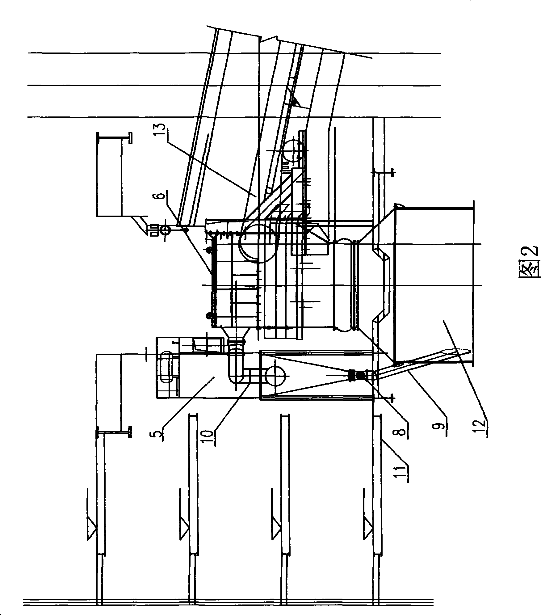
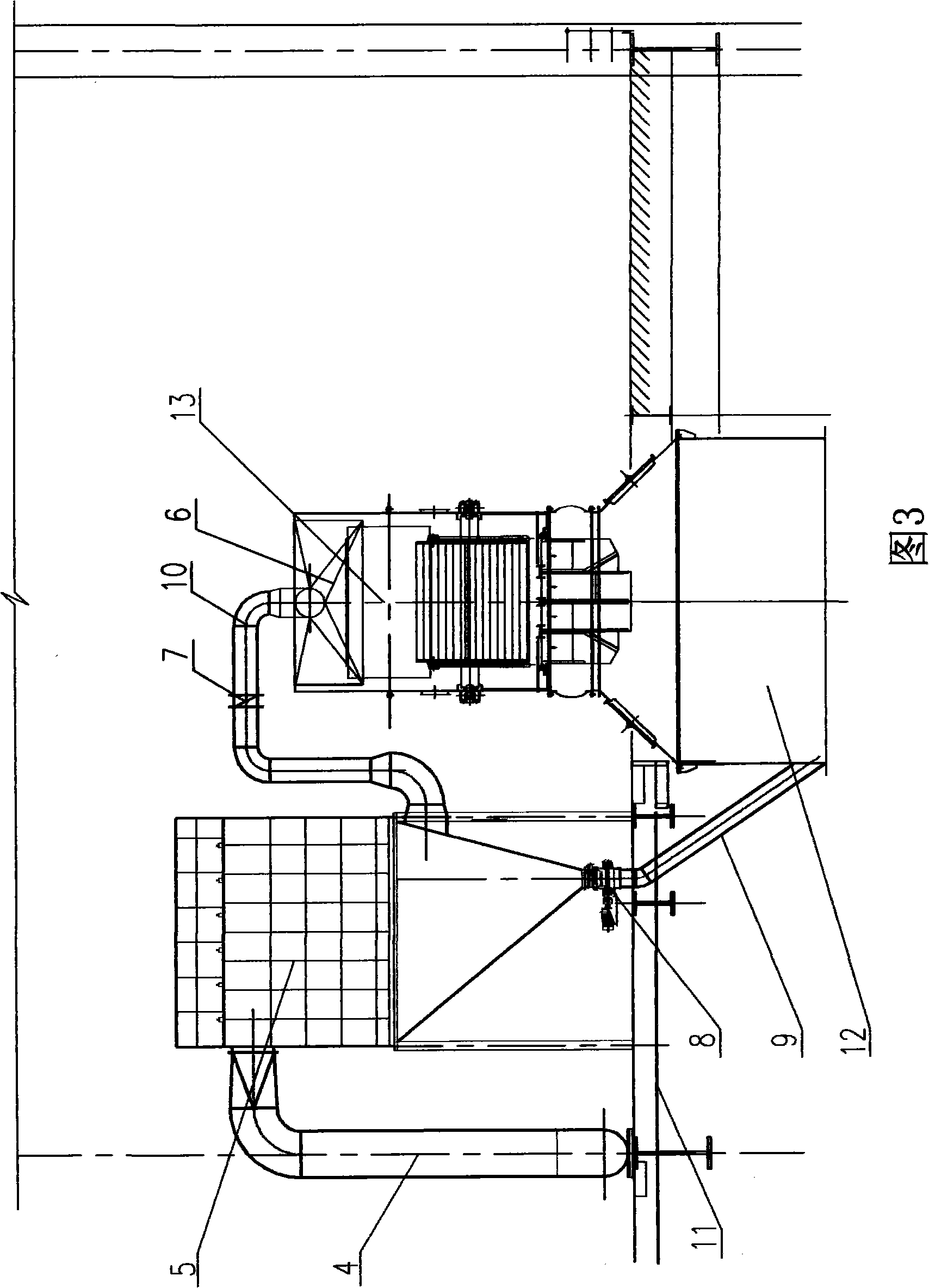
[0020] A blast furnace roof dedusting device, comprising a blower fan 1, a motor 2, a dust collector 5 and an airtight exhaust hood 6, the airtight exhaust hood 6 is arranged on the head of a belt conveyor 13, the blower fan 1 is driven by the motor 2, and The outlet of wind cover 6 is provided with first pipeline 10, and the other end of first pipeline 10 is connected with the inlet of dust collector 5, and above-mentioned fan 1, motor 2 and dust collector 5 are all arranged on blast furnace top platform 11, and dust collector 5 A second pipeline 4 is provided between the outlet of the dust collector 5 and the blower fan 1, a dust discharge valve 8 is provided at the outlet of the ash hopper of the dust collector 5, and a dust discharge pipe 9 is arranged on the dust discharge valve 8, and the dust discharge pipe The outlet of 9 communicates with the blast furnace charging tank 12 , an air volume regulating valve 7 is provided on the first pipeline 10 , and a vibration-damping...


PUM


Abstract

The invention discloses a blast furnace top dust removing plant, which comprises a blower (1), a motor (2), a dust catcher (5) and an obturation exhaust hood (6). The obturation exhaust hood (6) is arranged at the head of an adhesive tape machine (13). The blower (1) is driven by the motor (2). A first pipe (10) is arranged at the outlet of the obturation exhaust hood (6), and the other end of the first pipe (10) is connected with the inlet of the dust catcher (5). The blower (1), the motor (2) and the dust catcher (5) are all arranged on the platform of a blast furnace top (11). A second pipe (4) is arranged between the outlet of the dust catcher (5) and the blower (1). The blast furnace top dust removing plant has the advantages that the structure is simple, the investment is low and the energy consumption is low. At the same time the recycled dust is directly used and the cycled integrated utilization of resources is realized.

Description

technical field [0001] The invention relates to a dust removal device, in particular to a blast furnace top dust removal device used for dust removal of a large blast furnace. Background technique [0002] At present, large-scale blast furnaces generally use belt conveyors to charge the blast furnace top material tank. When charging, due to the large drop of materials, the tank is under positive pressure after feeding, so the gas containing a large amount of dust flows from the material tank. The feed port escapes, seriously polluting the environment around the tank. [0003] At present, the following three methods are usually used for the collection and purification of the dust emitted when the belt conveyor is used to load and unload the blast furnace top material tank for the above large blast furnaces: 1) set a dust cover at the head of the belt machine, There is an exhaust pipe on the top, and this part of the air volume is connected to the dust removal system of the c...

Claims


Application Information

Patent Timeline
IPC IPC(8): C21B7/22
Inventor 詹茂华
Owner HUATIAN ENG & TECH CORP MCC
Why Eureka
Try Eureka