Headlight for motor-driven vehicle

A technology for headlights and motor vehicles, which is applied in the direction of headlights, vehicle lighting systems, lighting devices, etc., can solve the problems of lower light energy utilization rate, large light-gathering capacity, and difficult processing, so as to improve processing quality, The processing technology is simple and the effect of improving the utilization rate

Inactive Publication Date: 2011-04-06
郭廷麟 +1
View PDF0 Cites 0 Cited by
  • Summary
  • Abstract
  • Description
  • Claims
  • Application Information

AI Technical Summary

Problems solved by technology

Although this technology achieves the light distribution requirements, it has the following disadvantages: 1. Only half of the light energy is used, that is, only the upper hemisphere or the lower hemisphere; 3. It is difficult to process two ellipsoids together, and it is difficult to process the seam into an ideal effect; 4. The condensers of motor vehicle headlights are all convex condensers. The imaging quality is poor, and the same light-gathering ability is large in size and heavy in quality.

Method used


Image

  • Headlight for motor-driven vehicle
  • Headlight for motor-driven vehicle
  • Headlight for motor-driven vehicle

Examples


Embodiment 1

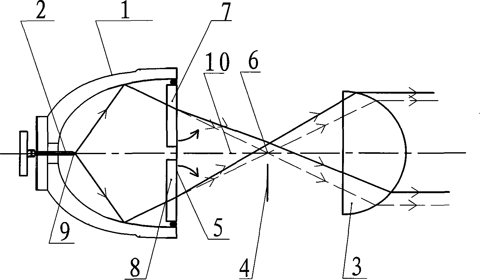
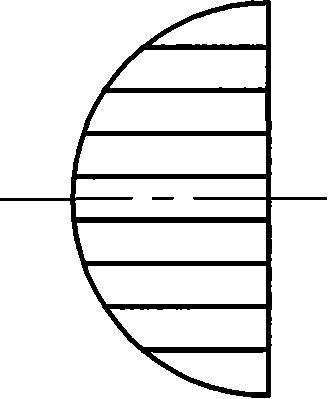
[0032] Such as figure 1 The motor vehicle headlight of the present invention as shown, comprises reflective mirror 1, and reflective mirror 1 is a rotating ellipse single curved surface reflector, is provided with light source 2 in reflective mirror 1, and light source 2 is located on the first focal point 9 of reflective mirror 1 A condenser 3 is provided in front of the reflector 1, the focus of the condenser 3 overlaps with the second focus of the reflector 1, and a baffle 4 is provided between the reflector 1 and the condenser 3, and the baffle 4 is located on the second focal point of the reflector 1. Below the two focal points 6, the top of the end face 5 optical axis 10 of the mirror 1 is provided with a first cylindrical lens 7, as Figure 7 , 8 The first cylinder 7 shown in , 9 and 10 is the combination of thread cylinder and wedge mirror; Projection angle α decreases to 0 from both ends to the center; the included angle between the wedge-shaped mirror ridge line 12...

Embodiment 2

[0035] A second lenticular lens 8 is arranged below the first lenticular lens 7 in Embodiment 1, and the second lenticular lens 8 is arranged below the end face 5 of the optical axis 10 of the mirror 1, as Figure 11 , 12 The second lenticular lens 8 shown in and 13 is the combination of a threaded lenticular lens and a wedge lens, and the second lenticular lens 8 is driven by an electromagnet; The wedge angle of the mirror is large, and the angle between the wedge-shaped mirror ridge line 12 and the threaded cylindrical mirror generatrix 11 is 45°,

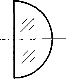
[0036] Such as Figure 5 The condenser lens 3 shown is a meniscus lens. Others are with embodiment 1.

Embodiment 3

[0038] The first lenticular lens 7 among the embodiment 2 is arranged on the end face 5 of reflective mirror 1 to the half place optical axis 10 between the second focal point 6 of reflective mirror 1, and the second lenticular lens 8 is located at the end face of reflective mirror 1 5 to the halfway between the second focal point 6 of the mirror 1 and below the optical axis 10, such as image 3 The first lenticular lens 7 and the second lenticular lens 8 shown are convex lenticular lenses, and the baffle plate 4, the first lenticular lens 7 and the second lenticular lens 8 are driven by motors. Others are with embodiment 2.


PUM


Abstract

The invention relates to a lamp, particularly a motor vehicle headlight. The motor vehicle headlight comprises a mirror reflector, a light source arranged inside the mirror reflector, a collecting mirror arranged in front of the mirror reflector, a baffle arranged between the mirror reflector and the collecting mirror, and a low beam horizontal refraction column lens arranged the optical axis from the end face to the focus of the mirror reflector. The motor vehicle headlight has the advantages that a rotating ellipse single-curved surface mirror reflector replaces two or more curved surface mirror reflector, thereby simplifying processing techniques, improving processing quality, ensuring processing accuracy, increasing reflecting power of the mirror reflector and increasing the utilization rate of luminous energy; the headlight can meet the standard of being wide horizontally and narrow vertically, thereby extending the lighting range of low beam of the motor vehicle headlight, doubling the illuminating brightness of the low beam; and low beam lighting can utilize all light energy so as to the power of the light source when the same illuminating brightness is reached, thereby achieving the effect of energy conservation and emission reduction.

Description

technical field [0001] The invention relates to a lighting lamp, in particular to a motor vehicle headlight. Background technique [0002] The national standard has strict requirements on the light distribution of motor vehicle headlights, and is limited by the national standard, such as: the illuminated range of the low beam lighting area is required to expand very wide in the horizontal direction and narrow in the vertical direction; In the high beam lighting area, light energy is required to be concentrated in the central area. [0003] At present, the light distribution of lighting lamps used in the market is far from meeting the requirements of light distribution standards, and most of them are high-power lighting lamps. The light source of the halogen tungsten lamp produced by German HELLA company is realized by the metal reflector. The reflector is spliced ​​by two half ellipsoids with different curvatures. Since the parameters of the two half ellipsoids are differen...

Claims


Application Information

Patent Timeline
Patent Type & Authority Patents(China)
IPC IPC(8): F21V5/04F21V7/00F21V13/00F21S8/10F21V11/18F21W101/10
CPCF21S48/1233F21V13/04F21W2101/10F21S41/25F21S41/40
Inventor 郭廷麟刘德润
Owner 郭廷麟
Why Eureka
Try Eureka