Endoscopic device
A technology for endoscopes and areas, applied in endoscopes, preparations for in vivo tests, pharmaceutical formulations, etc., can solve problems such as undisclosed signal processing, increased light in the red wavelength region, undisclosed signal processing, etc.
- Summary
- Abstract
- Description
- Claims
- Application Information
AI Technical Summary
Problems solved by technology
Method used
Image
Examples
Embodiment 1
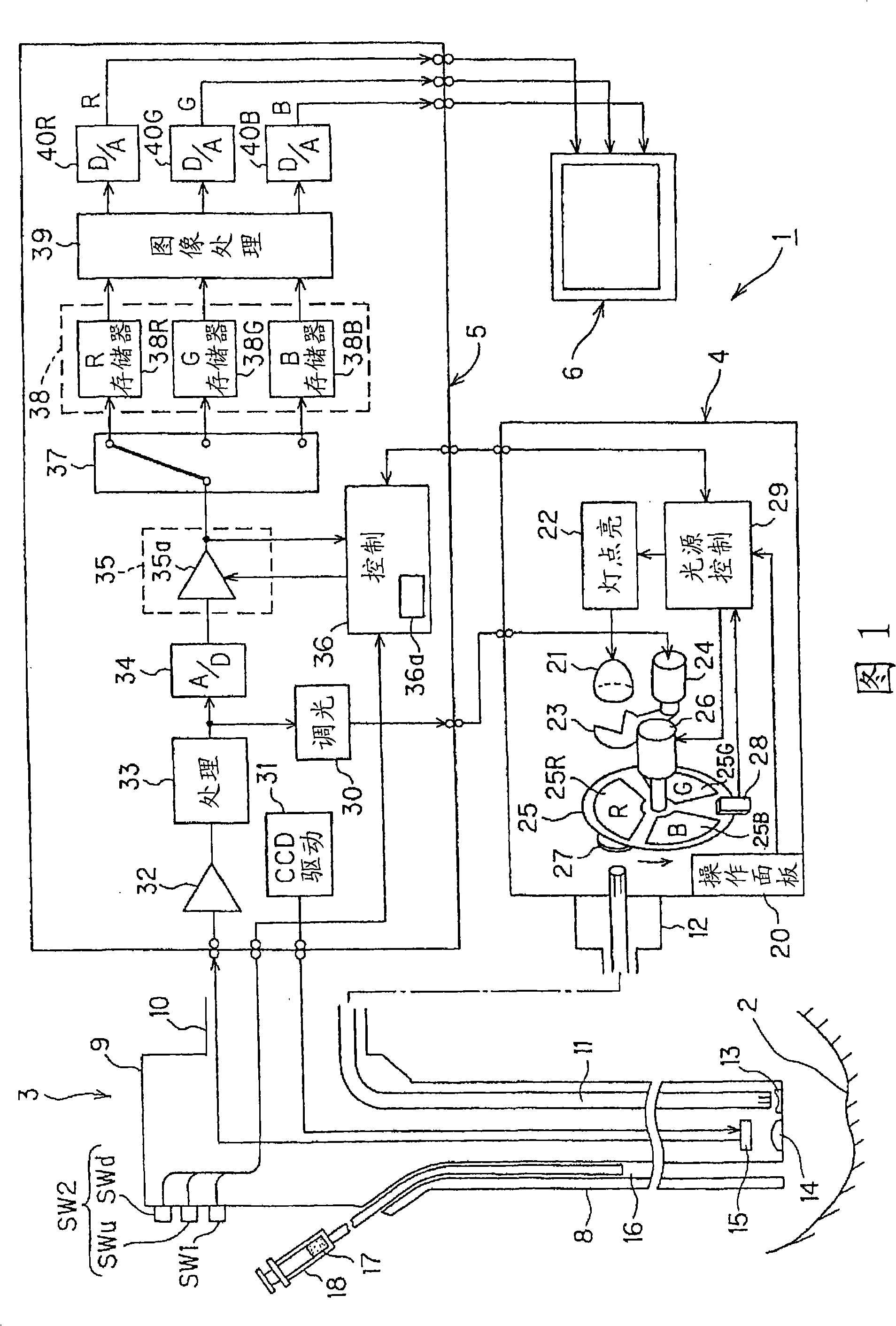
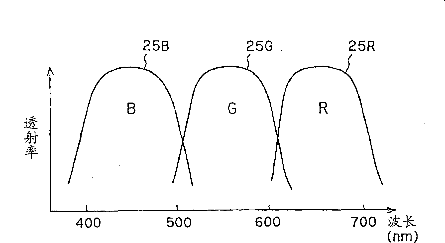
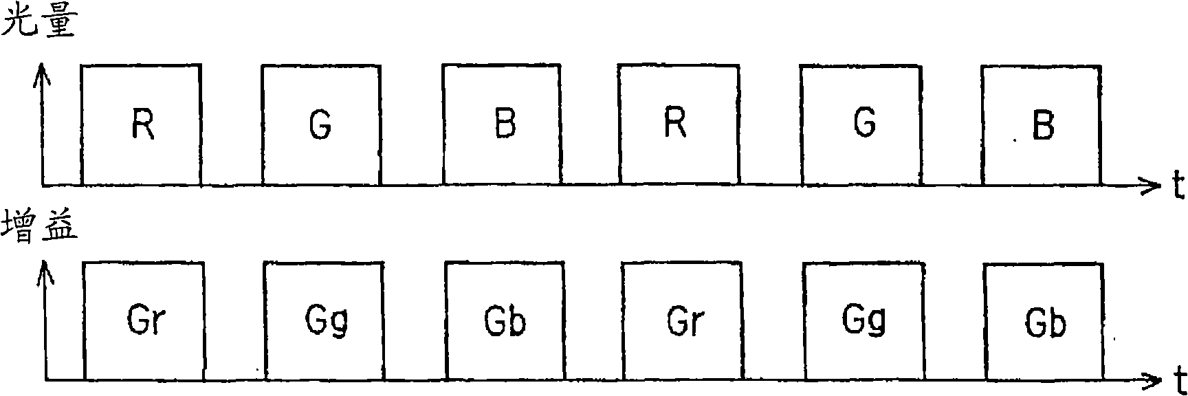
[0033] Refer to Figure 1 to Figure 4B Example 1 of the present invention will be described.
[0034] As shown in Figure 1, the endoscope device 1 of Embodiment 1 of the present invention comprises: electronic endoscope (hereinafter abbreviated as endoscope) 3, and it can be inserted in the body cavity, to the observation object such as the affected part in the body cavity The part 2 is photographed for endoscopic observation, etc.; the light source device 4 is detachably connected to the endoscope 3 to generate illumination light for observation; the processor 5 is detachably connected to the endoscope 3 The scope 3 is connected, and performs signal processing and the like for the captured image signal; and the monitor 6, which is connected to the processor 5, is input with the image signal output from the processor 5, and displays the image corresponding to the image signal. image.
[0035] The endoscope 3 has an elongated insertion portion 8 inserted into a body cavity, a...
Embodiment 2
[0095] Next, Embodiment 2 of the present invention will be described with reference to FIGS. 5 and 6 . FIG. 5 shows the configuration of a simultaneous endoscope device 1B according to the second embodiment.
[0096] This endoscope device 1B is composed of an endoscope 3B, a light source device 4B, a processor 5B, and a monitor 6 .
[0097] The endoscope 3B is a simultaneous type endoscope having a color imaging CCD provided with a color separation filter 51 on the imaging surface of the CCD 15 in addition to the endoscope 3 of FIG. 1 . And, in the operation part 9 of this endoscope 3B, similar to the case of the first embodiment, there are provided: a mode switching switch SW1, which is used to switch to the first observation mode corresponding to normal observation; a light amount increase switch SWu, It performs an instruction operation to increase the light quantity of the red illumination light in the second observation mode, and a light quantity reduction switch SWd for...
Embodiment 3
[0122]Embodiment 3 of the present invention will be described below with reference to FIG. 7 . Example 3 has a structure in which, for example, a part of Example 2 is changed. FIG. 7 shows the structure of a light source device 4C in Embodiment 3. As shown in FIG. This light source device 4C has a structure in which, for example, in the light source device 4B in FIG. Optionally configured in the illumination light path.
[0123] The operation of the filter insertion and removal device 61 is controlled by the light source control circuit 29 . In this embodiment, the state in which no filter is disposed in the illumination optical path corresponds to the state in which the transparent portion 53T is disposed in the illumination optical path in Embodiment 2, that is, normal observation.
[0124] Then, when the first filter 62a or the second filter 62b is disposed in the illumination optical path by the filter insertion and removal device 61, the first bandpass filter 53A or th...
PUM
 Abstract
Description
Claims
Application Information
 - R&D
- Intellectual Property
- Life Sciences
- Materials
- Tech Scout
- Unparalleled Data Quality
- Higher Quality Content
- 60% Fewer Hallucinations
Browse by: Latest US Patents, China's latest patents, Technical Efficacy Thesaurus, Application Domain, Technology Topic, Popular Technical Reports.
© 2025 PatSnap. All rights reserved.Legal|Privacy policy|Modern Slavery Act Transparency Statement|Sitemap|About US| Contact US: help@patsnap.com


