Method and equipment for multiplexing and demodulating long period optical fiber optical grating array

A fiber grating array, fiber grating technology, which is applied in the direction of light demodulation, cladding fiber, optical waveguide light guide, etc., to achieve the effect of low cost and high measurement accuracy

Inactive Publication Date: 2008-09-24
ZHEJIANG UNIV
View PDF0 Cites 17 Cited by
  • Summary
  • Abstract
  • Description
  • Claims
  • Application Information

AI Technical Summary

Problems solved by technology

For the same reason, so far, no one has proposed a long-period fiber grating multiplexing real-time sensing system based on optical frequency domain reflectometry

Method used


Image

  • Method and equipment for multiplexing and demodulating long period optical fiber optical grating array
  • Method and equipment for multiplexing and demodulating long period optical fiber optical grating array
  • Method and equipment for multiplexing and demodulating long period optical fiber optical grating array

Examples


Embodiment Construction

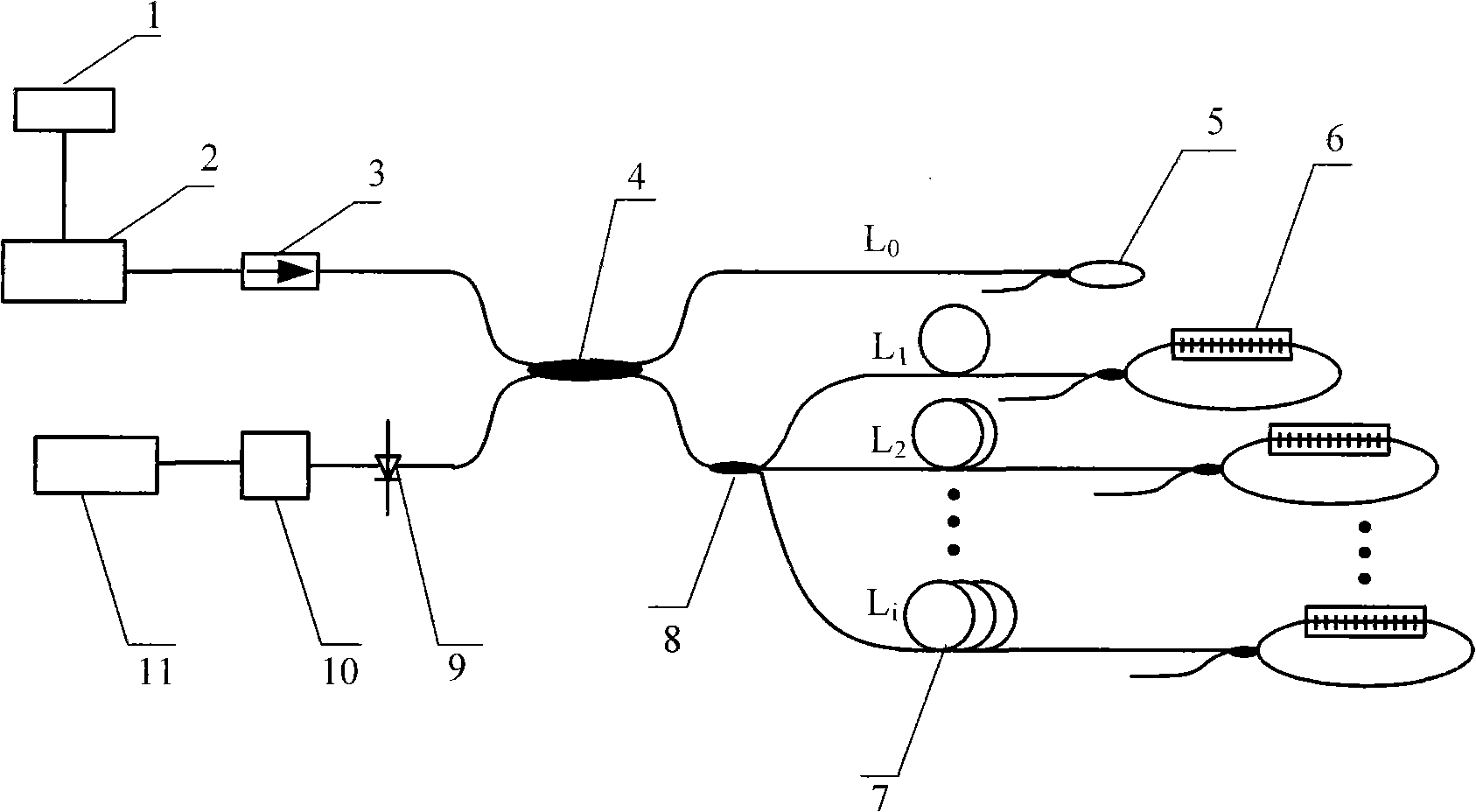
[0033] Such as figure 1 As shown, the output end of the digital signal generator 1 is electrically connected to the current driving end of the semiconductor laser 2 . The semiconductor laser 2 is optically connected to an input port of a 2×2 fiber coupler 4 through an optical isolator 3 . An output port of the optical fiber coupler 4 is optically connected to an input end of the optical fiber loop reflector 5 after passing through a certain length of compensation optical fiber. The other output port of the fiber coupler 4 is optically connected to the input port of the 1×n coupler 8 . After each output port of the coupler 8 is optically connected with delay lines 8 of different lengths, they are respectively optically connected with fiber optic loop reflectors fused with long-period fiber gratings 6 . The other input port of the fiber coupler is optically connected to the input end of the photodiode 9 , and the output end of the photodiode 9 is electrically connected to the ...


PUM


Abstract

The invention relates to a real time signal multiplexing and demodulating method of a sensor of a full optical fiber long period optical fiber raster array and a device thereof. The invention selects the continuous laser as an optical source, which is provided with the central wavelength at an optical fiber communication wave bond and has an adjustable single longitudinal mode; the frequency of the laser sent by the optical source is demodulated, and then the laser is distributed to a reference light path and a measuring light path by an optical fiber isolator and an optical fiber coupler according to light intensity fixed proportion. The laser entering the reference light path is all reflected by a FLM. The laser entering the measuring light path is distributed into the branch measuring light path of i path, and the light intensity introduced by LPG after waste is reflected by the FLM. The light intensity reflected by each branch measuring light path is coupled and then passes through a 2 is multiplied by 2 optical fiber coupler again together with the light intensity reflected by the reference light path to produce a beat frequency signal. The wavelength drift rate of the central wavelength of the corresponding LPG is confirmed by analyzing the beat frequency signal. The method has the high measuring precision, has the advantage of low cost and is suitable for the integration and the instrumentation.

Description

technical field [0001] The invention belongs to the technical field of optical fiber sensing, and relates to a real-time signal multiplexing and demodulation method of a sensor of an all-fiber long-period fiber grating array, and equipment for realizing the method. Background technique [0002] In the field of optical fiber sensing, long-period fiber grating (long-period grating, LPG) has become a very important sensing device in the industry due to its sensitivity to changes in microbending, temperature, stress, and refractive index, especially for liquid refraction. High-precision measurement of rate. [0003] Optical Frequency-Domain Reflectometry (OFDR) modulates the frequency of the continuous light emitted by the laser light source, and then detects the beat frequency based on the light reflected from the optical fiber or the component under test, so it only requires low frequency The demodulation equipment has a small beat frequency, which reduces the cost and mainta...

Claims


Application Information

Patent Timeline
Patent Type & Authority Applications(China)
IPC IPC(8): G02F1/35G02F2/00G02B6/02G02B6/26G01D5/26G01D5/353
Inventor 姜萌陈达如何赛灵
Owner ZHEJIANG UNIV
Why Eureka
Try Eureka