
Equipment and process for preparing polymer water source by katalysis deactivation of oilfield sewage

A technology of oilfield sewage and polymerization, applied in the direction of oxidized water/sewage treatment, physical/chemical process catalyst, metal/metal oxide/metal hydroxide catalyst, etc., can solve the impact and limit the popularization and application of polymer flooding technology, etc. question

Active Publication Date: 2008-10-01
PETROCHINA CO LTD
View PDF0 Cites 2 Cited by
  • Summary
  • Abstract
  • Description
  • Claims
  • Application Information

AI Technical Summary

Problems solved by technology

[0003] Therefore, the current problem of viscosity reduction in sewage has seriously affected and limited the popularization, application and further development of polymer flooding technology.

Method used


Image

  • Equipment and process for preparing polymer water source by katalysis deactivation of oilfield sewage
  • Equipment and process for preparing polymer water source by katalysis deactivation of oilfield sewage
  • Equipment and process for preparing polymer water source by katalysis deactivation of oilfield sewage

Examples


preparation example Construction

[0029] The preparation process of this scheme is as follows: figure 1 shown. The incoming water that meets the control standard 1 in Table 1 is first filtered through a fine filter, and the filtered water reaches the control standard 2 in Table 1; then it is treated by a catalytic oxidation deactivation device, and the treated sewage reaches the control standard 3 in Table 1. It can be directly used to prepare polymer solution.

[0030] Table 1 Production Process Control Indicators

[0031]

[0032] Option II

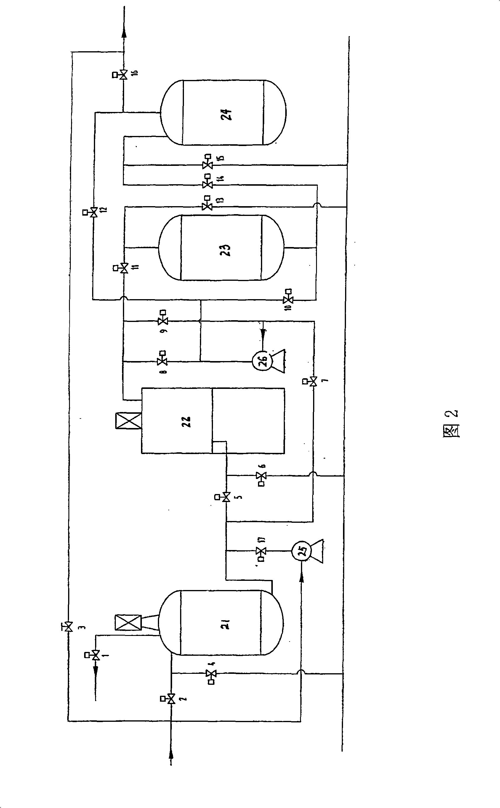
[0033] The flow of this program is shown in Figure 2. On the basis of scheme 1, a preliminary filtration step through a walnut shell filter is added before the fine filtration step, and a preliminary iron removal step is performed with an iron removal filter device filled with manganese sand and quartz sand before the catalytic oxidation deactivation step. The valve actions are shown in Table 2. Valve 1 is the oil discharge valve, valve 2 is the electric valve of...

Embodiment 1

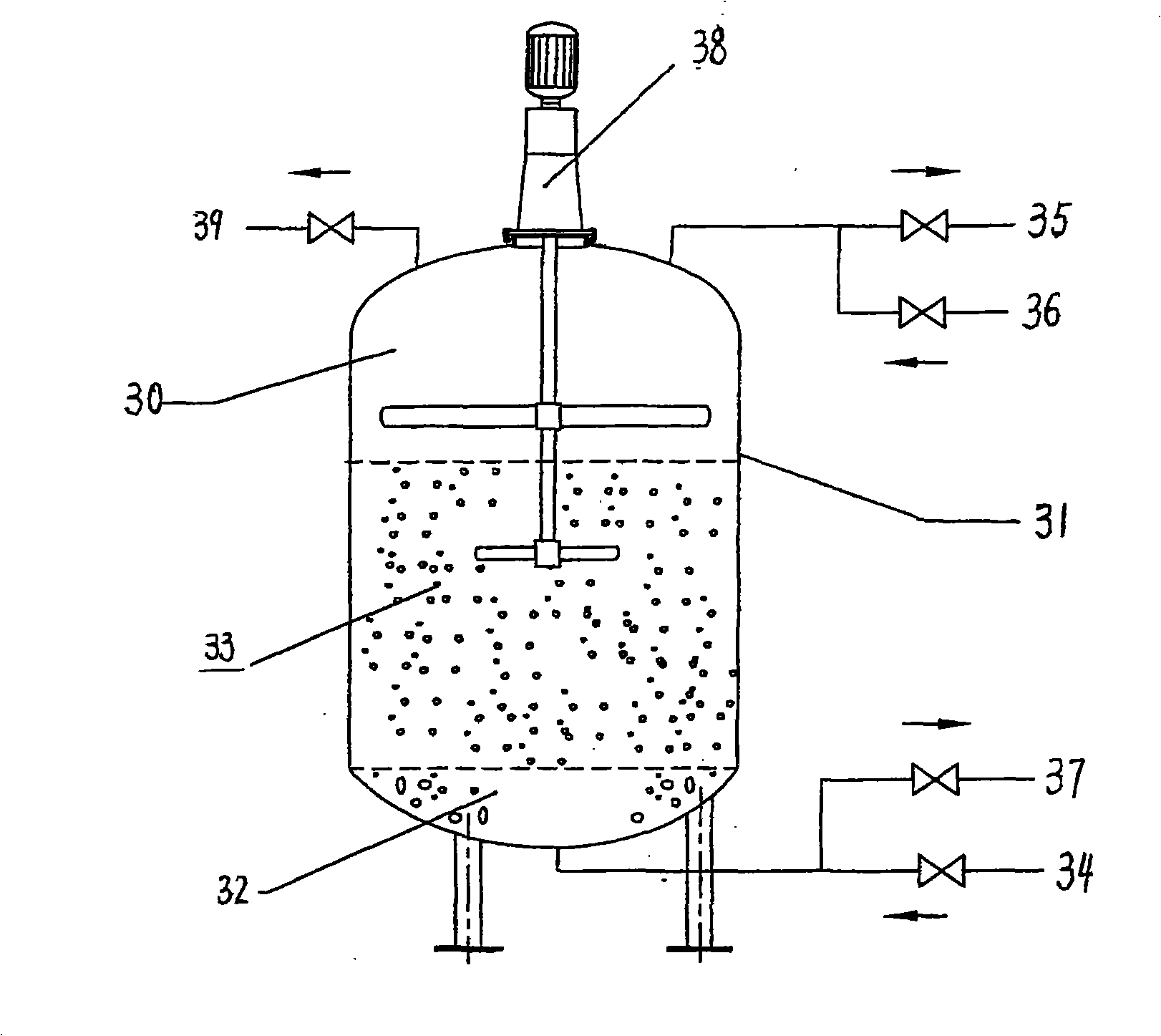
[0110] MnO 2 -ZnO-CeO 2 / Al 2 O 3 Preparation of catalyst

[0111] The diameter is 1.6mm and the specific surface area is 150m 2 / g Al 2 O 3 The carrier is in Mn(NO 3 ) 2 , Zn(NO 3 ) 2 and Ce(NO 3 ) 3 The molar concentrations of the three nitrates in the solution are shown in Table 4. After drying at 150°C for 4 hours, it was calcined at 650°C for 3 hours. That is to get MnO 2 -ZnO-CeO 2 / Al 2 O 3 catalyst.

[0112] Table 4 Nitrate solution molarity

[0113] Mn(NO 3 ) 2 (mol / L)

Embodiment 2

[0115] Catalytic deactivation unit to treat fresh flowing sewage in Hanan Oilfield

[0116] The fresh flowing sewage from Hanan Oilfield was treated with preliminary oil removal to meet the requirements of control standard 1 in Table 1 above. The process and equipment of the first solution of the present invention are used for treatment. The catalyst 1 prepared in Example 1 was used as the filler in the catalyst tank.

[0117] The polymer HPAM (molecular weight: 25 million) was added to the water before and after the treatment to prepare a polymer solution with a concentration of 1 g / L.

[0118] See the test results Figure 7 and Figure 8 , Obviously, the viscosity of the polymer solution prepared by the catalytic deactivation technology to treat the fresh flowing sewage of Hanan Oilfield is about 300% higher than that of the untreated sewage.


PUM

PropertyMeasurementUnit
Particle sizeaaaaaaaaaa
Diameteraaaaaaaaaa
Specific surface areaaaaaaaaaaa

Abstract

The invention provides equipment and a technique for preparing confecting polymer water sources by catalyzing wastewater in oil fields for deactivation. The equipment consists of a walnut shell filter, in which cobbles and walnut shell fillings are filled, a TCLW filter, in which fibrous bundles are filled, an iron removing tank, in which manganese sand and quartz sand fillings are filled, a catalyzing reaction tank, the structure of which is a maze and in which a catalyzer MnO2-ZnO-CeO2 / Al2O3 is filled, connecting pipelines and valves between the walnut shell filter, the TCLW filter, the iron removing tank and the catalyzing reaction tank. The lower part outlet of the walnut shell filter is connected with the lower part inlet of the TCLW filter through a pipeline, the upper outlet of the TCLW filter is connected with the top inlet of the iron removing tank through a pipeline and the bottom outlet of the TCLW filter is connected with the top inlet of the catalyzing reaction tank. The technique has stable and safe operation, simple operation, convenient management, reasonable investment, being economic and high efficient, and complies with environmental protection requirements. After catalysis and deactivation, the viscosity of wastewater confecting polymer solution is improve by over 100 percent and the rate of utilization of wastewater confecting polymer is up to 100 percent.

Description

technical field [0001] The invention relates to equipment and a process for preparing a compounding water source through catalytic deactivation of oilfield sewage. Background technique [0002] In recent years, oilfield polymer flooding technology has entered the stage of full industrialization and has become one of the important successor technologies for the sustainable development of waterflood development oilfields. During the implementation of polymer flooding technology, how to maintain sufficient viscosity of injected solution is the core issue throughout this technology, and it is also one of the important contents of polymer flooding technology research. In order to maintain the viscosity of the polymer injection fluid, the current practice in most oilfields in my country is to use ultra-high molecular weight polymers, and at the same time use the clean water injection process. Since the content of divalent ions sensitive to polymers in clear water is low and does ...

Claims


Application Information

Patent Timeline
IPC IPC(8): C02F1/72B01J23/34B01J21/04C02F103/10
Inventor 韩冬韦莉伍家忠林庆霞罗文利樊剑
Owner PETROCHINA CO LTD
Learn More