Oil gas well completion temporary blocking liner tube

A technology for oil and gas wells and liners, which is applied in wellbore/well components, production fluids, earthwork drilling and production, etc. It can solve problems such as well wall collapse, large liner deformation, and unusable wellbore, so as to reduce perforation, The effect of speeding up the pace and saving the cost of perforating

Inactive Publication Date: 2008-10-01
BC P INC CHINA NAT PETROLEUM CORP +1
View PDF1 Cites 7 Cited by
  • Summary
  • Abstract
  • Description
  • Claims
  • Application Information

AI Technical Summary

Problems solved by technology

[0002] At present, underbalanced drilling, snubbing and tripping under pressure, underbalanced coring, and snubbing and pressure logging in the whole process of underbalanced drilling technology have become increasingly mature, but the underbalanced completion method is still Relatively simple, the main completion methods are open hole completion and liner completion. The open hole completion method has the advantages of fast and economical, but its disadvantages are: it can only be implemented in the harder layers of underground rock, and Open hole completion in soft and loose formations will lead to wellbore collapse and eventually make the wellbore unusable; using liner to complete the well without cementing is a common way at present, but it needs to be well cleaned. The perforated pipe is used to make it a liner with holes so that the downhole oil and gas resources can enter the tubing and be recovered to the surface. Well cementing is in an unfixed state and is not centered in the well. This will cause the pin of the one-way constant pressure joint of the tubing to be lowered in the future. It has brought trouble to the follow-up work. A patent application with the patent application number 200520113354.3 discloses a well completion device for underbalanced well completion. The patent is to pre-cut non-penetrating bar shafts ...

Method used


Image

  • Oil gas well completion temporary blocking liner tube

Examples


Embodiment Construction

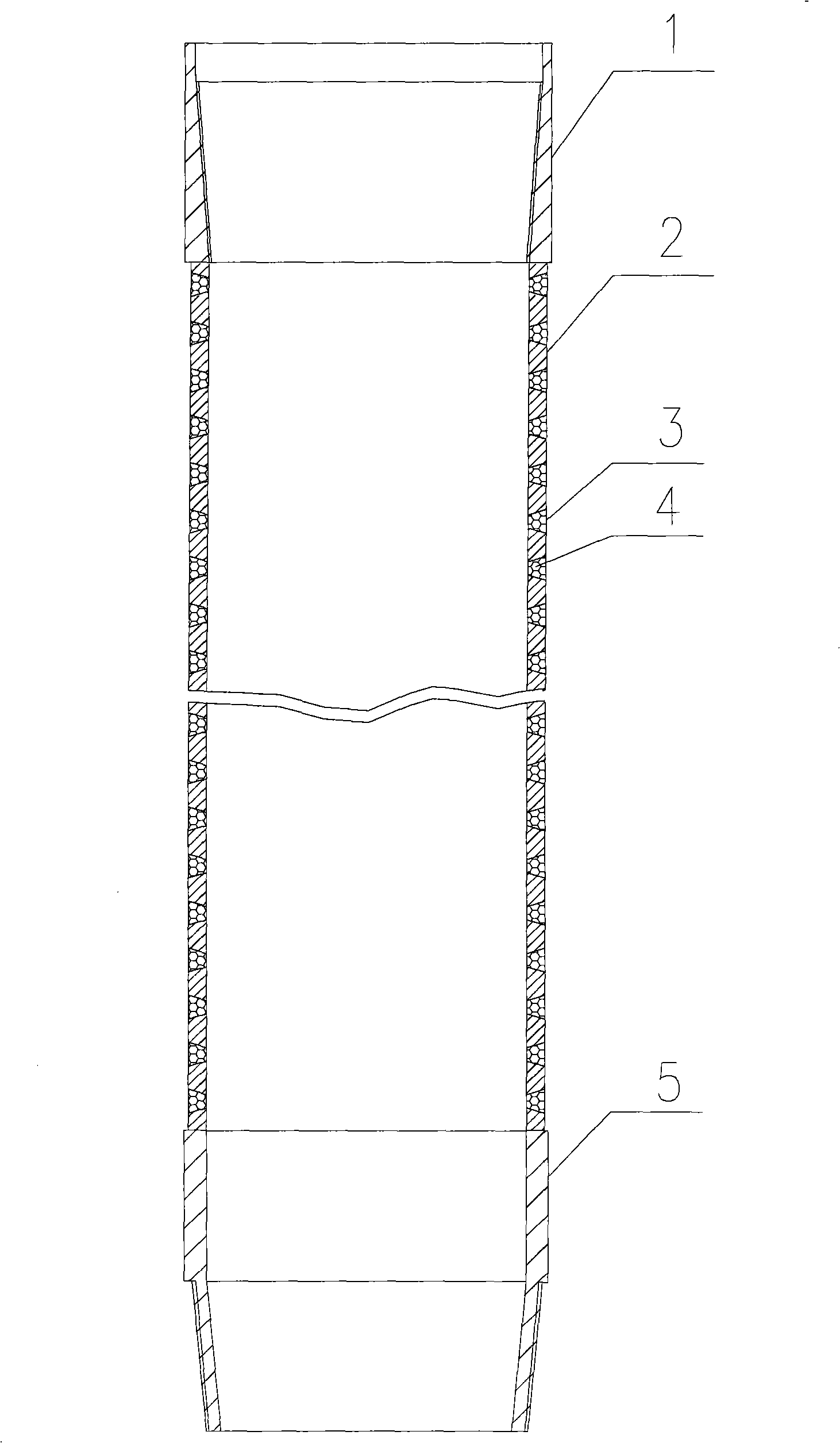
[0007] Provide the embodiment of the present invention below in conjunction with accompanying drawing: the present invention comprises pipe body 2 and joint, the two ends of pipe body are provided with upper joint 1 and lower joint 5, have the conical cone of 8-10mm on the circumference of pipe body 2 Shaped sieve hole 3, the conical sieve hole 3 that runs through the pipe body 2 is conical, the diameter of a hole on the inner wall of the pipe 80°C; the specific implementation method is: on site according to the needs Determine the required length of the pipe string, and then drill the tapered screen hole 3 through the inside and outside of the pipe body 2 of the ordinary casing according to the size of the gas volume, so that the screen pipe with the screen hole 3 is made. Due to the implementation of underbalanced Running the pipe string under pressure needs to prevent the crude oil or natural gas in the well from entering the pipe through the screen holes during the running ...


PUM

PropertyMeasurementUnit
Melting temperatureaaaaaaaaaa

Abstract

The invention relates to an oil and gas well completion temporary plugging lining pipe, which is used for the under-balanced well completion after under-balanced drilling, belonging to the field of whole process under-balanced drilling well completion snubbing manufacturing technology. Based on the characteristic that temporary plugging agent can melt under high temperature, the invention designs an oil and gas well completion temporary plugging lining pipe which has an upper joint and a lower joint, and is equipped with through sieve pores with temporary plugging agent inside on the pipe body, solves the problem that a tail pipe is perforated in the prior art, resulting in tail pipe deformation, and is in an unfixed state in a well, bringing in trouble to subsequent works, the sieve pores of the temporary plugging lining pipe are processed on the ground, thus the temporary plugging lining pipe has the characteristics of convenient process and deformation improbability, a different binder can be selected in accordance with a different well depth to implement temporary plugging, after the lining pipe is put in the well, the temporary plugging agent can melt slowly when the temperature in the well reaches to a preset value, thus a temporary lining pipe having sieve pores can be obtained.

Description

Technical field: [0001] An oil and gas well completion temporary plugging liner is used for underbalanced drilling and completion after underbalanced drilling, and belongs to the technical field of design and manufacture of underbalanced drilling and completion pipe strings in the whole process. Background technique: [0002] At present, underbalanced drilling, snubbing and tripping under pressure, underbalanced coring, and snubbing and pressure logging in the whole process of underbalanced drilling technology have become increasingly mature, but the underbalanced completion method is still Relatively simple, the main completion methods are open hole completion and liner completion. The open hole completion method has the advantages of fast and economical, but its disadvantages are: it can only be implemented in the harder layers of underground rock, and Open hole completion in soft and loose formations will lead to wellbore collapse and eventually make the wellbore unusable...

Claims


Application Information

Patent Timeline
IPC IPC(8): E21B43/08
Inventor 杨令瑞肖新宇肖润德李艳丰杨玻
Owner BC P INC CHINA NAT PETROLEUM CORP
Why Eureka
Try Eureka