High precision split joint sub lens relative tilt error photo-electric detection system

A tilt error, photoelectric detection technology, applied in the relative field between spliced ​​sub-mirrors, can solve the problems of insufficient detection accuracy, practicability, and operability, achieve high-quality imaging promotion, improve observation efficiency, and detection accuracy. high effect

Inactive Publication Date: 2008-10-01
INST OF OPTICS & ELECTRONICS - CHINESE ACAD OF SCI
View PDF0 Cites 28 Cited by
  • Summary
  • Abstract
  • Description
  • Claims
  • Application Information

AI Technical Summary

Problems solved by technology

However, the detection accuracy, practicability, and operability of the...

Method used


Image

  • High precision split joint sub lens relative tilt error photo-electric detection system
  • High precision split joint sub lens relative tilt error photo-electric detection system
  • High precision split joint sub lens relative tilt error photo-electric detection system

Examples


Embodiment Construction

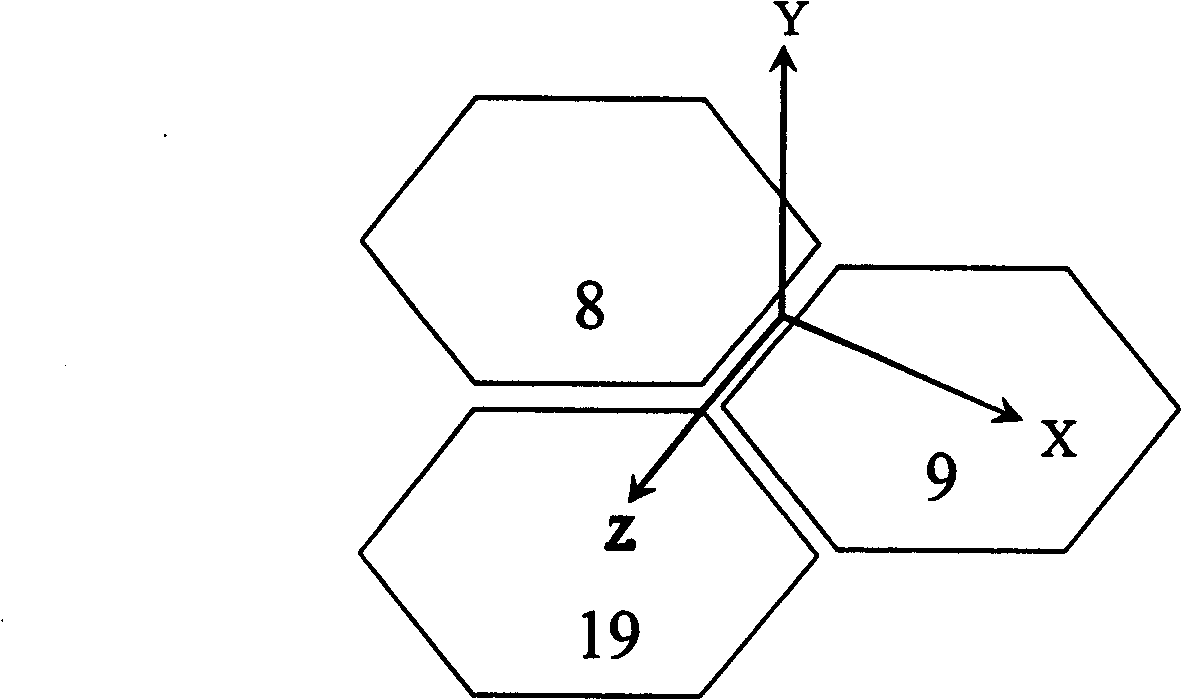
[0017] figure 1 It is an analysis diagram of the degree of freedom of splicing sub-mirrors in a large-aperture telescope in a three-dimensional coordinate system. The relative tilt error between the sub-mirrors around the X-axis is called tilt error, and the relative tilt error between sub-mirrors around the Z-axis is called tip error. figure 1 Shown in is the three sub-mirror splicing main mirror, wherein 8, 9, and 19 represent the first, second and third sub-mirrors respectively.

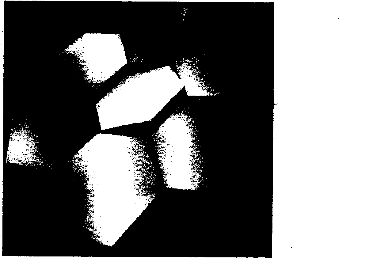
[0018] Such as figure 2 as shown, figure 2 It is a schematic diagram of the surface shape of a large-aperture telescope when there is a tilt error between the spliced ​​sub-mirrors, in which the six peripheral sub-mirrors represent the situation where the coplanar arrangement has been realized, and the middle sub-mirror is not coplanarly arranged, that is, relative to the surrounding six sub-mirrors The situation when there is a tilt error in the sub-mirror.

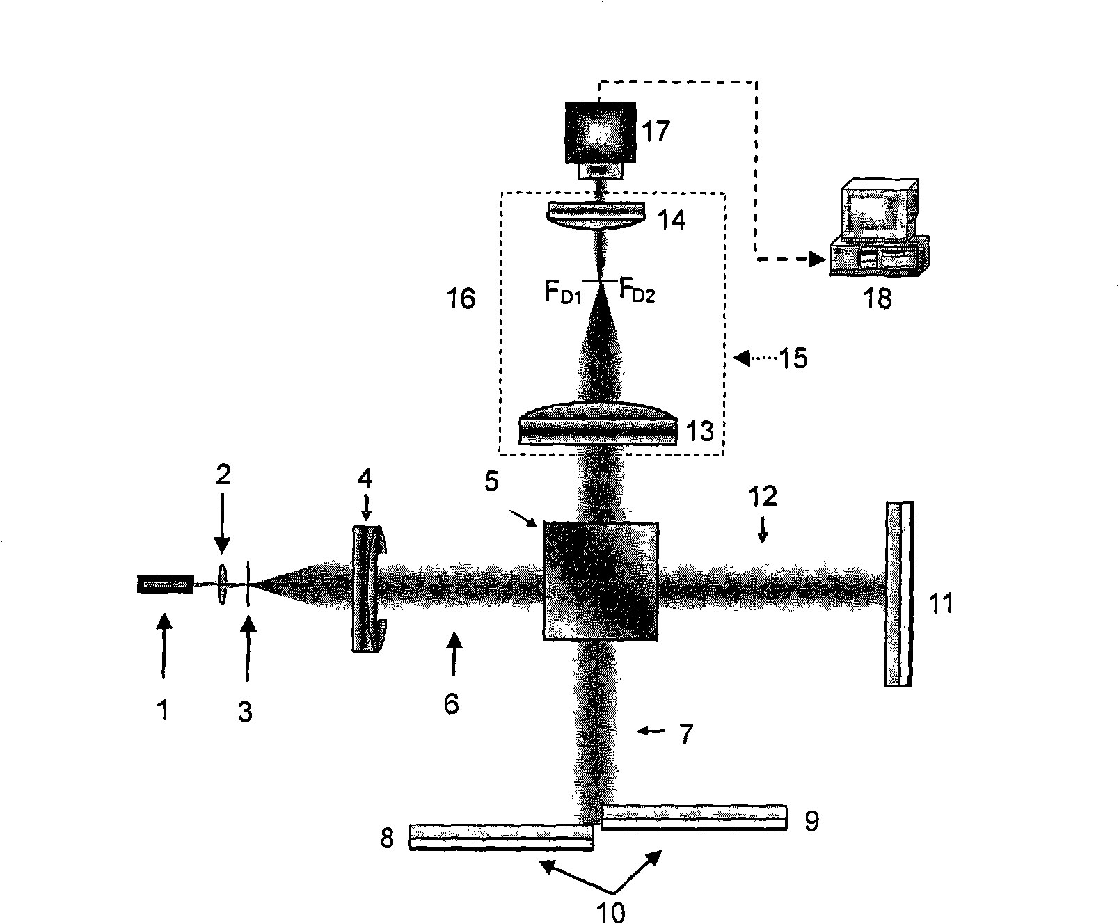
[0019] Such as image 3 As show...


PUM

PropertyMeasurementUnit
Wavelengthaaaaaaaaaa

Abstract

A high-precision splitting sub-mirror relative inclining error photoelectric detection system comprises the following components: a HE-NE laser, a spatial filter, a collimator objective, a cubic beam splitting prism, a detected splitting sub-mirror set, a reference mirror, a light path beam-contracting system, a CCD planar array photoelectric detector and a data processing system. The HE-NE laser, the spatial filter and the collimator objective form a light source arm part of the detection system together. The detected splitting sub-mirror set forms a measuring arm part of the detection system. The reference reflecting mirror forms a reference arm part of the detection system. The relative inclining error information which is detected by the detecting arm and is between the splitting sub-mirrors is detected by the CCD planar array photoelectric detector. The detected interference image information is processed by a data processing system for real-time detecting the inclining error between the splitting sub-mirrors. The invention can execute a real-time high-precision detection. The effect of the relative inclining error between the sub-mirrors to the imagining quality of the telescope can be reduced with a large scale and the invention has the advantage of simple structure.

Description

technical field [0001] The present invention is a set of relative inclination error detection system between spliced ​​sub-mirrors based on interference system, which is mainly aimed at real-time detection of relative inclination errors between spliced ​​sub-mirrors of large-aperture telescopes, and the detected data information is processed by a data processing system. Corresponding processing is carried out to extract the relative tilt error between the sub-mirrors, so that it can be corrected by a correction system, which is generally a PZT (piezoelectric ceramic device) correction device. Background technique [0002] In the field of astronomical observation, it is necessary to detect more distant celestial bodies, so it is necessary to develop telescopes with larger apertures and higher imaging quality. Due to the difficulty of processing and the limitations of related technologies, it is generally believed that the limit aperture of the entire primary mirror of a large...

Claims


Application Information

Patent Timeline
IPC IPC(8): G02B27/00G02B23/00G01M11/02G01C9/00
Inventor 宋贺伦李华强鲜浩黄健李超宏姜文汉
Owner INST OF OPTICS & ELECTRONICS - CHINESE ACAD OF SCI
Why Eureka
Try Eureka