Dry-type phase-change thermal storage floor heating terminal device

A phase change heat storage and terminal device technology, which is applied in hot water central heating systems, heating methods, electric heating systems, etc., can solve the problems of low utilization rate of phase change materials, ineffective heating rate, and downward heat leakage from the floor, etc. Achieve the effect of saving space, reducing building bulk density, and increasing thermal resistance

Inactive Publication Date: 2008-10-08
TSINGHUA UNIV
View PDF1 Cites 24 Cited by
  • Summary
  • Abstract
  • Description
  • Claims
  • Application Information

AI Technical Summary

Problems solved by technology

However, in this method, the heating rate cannot be adjusted according to the heating load; the heating and heat release of phase change materials is a one-way heat release process, and the utilization rate of phase change materials is not high; the heat leakage from the floor is serious, etc.

Method used


Image

  • Dry-type phase-change thermal storage floor heating terminal device
  • Dry-type phase-change thermal storage floor heating terminal device
  • Dry-type phase-change thermal storage floor heating terminal device

Examples


Embodiment Construction

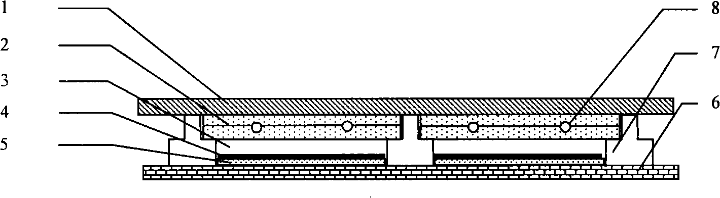
[0020] A dry-type phase change heat storage floor heating terminal device of the present invention, such as figure 1 Shown, below in conjunction with accompanying drawing, describe in detail as follows:

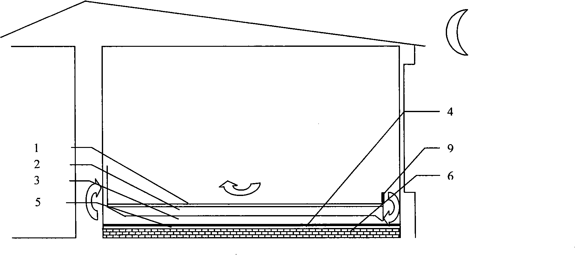
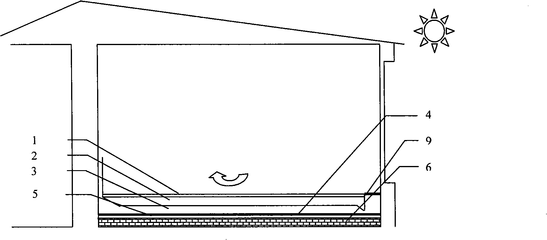
[0021] The floor decoration layer 1 is supported by the keel 7, and the bottom of the floor decoration layer 1 is a phase-change material layer 2, an air channel 3, a radiation-proof film 4, an insulation layer 5 and a floor base layer 6 in order from top to bottom. In the phase change material layer 2 between a group of adjacent keels 7, at least one water supply pipe 8 or an electric heating film is buried. The phase-change material layer between adjacent keels can be in close contact with the floor decoration layer or an air layer can be reserved. The phase change material should completely cover the outer wall of the water supply pipe 8, or the upper and lower surfaces of the electric heating film. The phase change material is divided into upper and lower layers. If it ...


PUM

PropertyMeasurementUnit
Phase transition temperatureaaaaaaaaaa

Abstract

The invention provides a phase-changing heat accumulation floor heating terminal device pertaining to building heating technique field. The invention employs phase-changing material as heat storage medium for heating. The device, from above to below, includes a floor decoration layer, a phase-changing material layer, an air duct, a radiation protection film, a thermal insulation layer and a floor base layer in turn; keels are arranged between the floor decoration layer and the floor base layer, at least a heat supply waterpipe or a electrical heating film are buried in the phase-changing material layer between adjacent keels; a wind gap is arranged at both ends of the air duct to communicate with indoor air. The phase-changing material supplies heat for indoor heating by heat conduction upwards and convection current, meanwhile heat supply of the phase-changing material is adjusted by air duct and indoor aeration speed, which further regulates and controls heat supply speed. The invention resolves defects of discommodity of heat supply speed adjustment of phase-changing floor energy storage mode, finity of phase-changing material availability, and the invention effectively decreases thermal transmission damage of floor heating downwards.

Description

technical field [0001] The patent of the present invention relates to a building heating technology, in particular to a structural design of an energy storage heating floor. Background technique [0002] Floor heating is a new heating method developed in recent years, mainly using ground radiation. It heats evenly, and people can feel the dual effects of radiation and convection heating at the same time, which is more comfortable than convection radiators and saves floor space. [0003] The water temperature of floor heating can reach the comfort level required by the human body at 40-50°C. Therefore, floor heating only needs a low-grade heat source, which is very suitable for using hot water provided by solar collectors as a heat source. Using hot water provided by solar energy as a heat source for heating in winter can greatly save the consumption of fossil energy, but there are problems of intermittent and discontinuous energy. The energy storage water tank used is large...

Claims


Application Information

Patent Timeline
IPC IPC(8): F24D3/12F24D13/02
CPCY02B30/24Y02B30/26Y02B30/00
Inventor 王馨曾若浪张寅平肖伟狄洪发杨睿张群力
Owner TSINGHUA UNIV
Why Eureka
Try Eureka