Magnetofluid flat plate hot pipe soaking device

A technology of flat heat pipes and magnetic fluids, applied in indirect heat exchangers, lighting and heating equipment, cooling/ventilation/heating transformation, etc., can solve problems such as insufficient capillary force and difficult arrangement of capillary cores, and achieve good heat uniformity, Increase the thermal efficiency of phase change and enhance the effect of boiling

Inactive Publication Date: 2008-10-08
BEIJING UNIV OF TECH
View PDF0 Cites 10 Cited by
  • Summary
  • Abstract
  • Description
  • Claims
  • Application Information

AI Technical Summary

Problems solved by technology

[0009] The invention aims to solve the shortcomings of difficult capillary core arrangement and insufficient capillary force in the traditional flat heat pipe heat spreader, and proposes a magnetic fluid flat heat pipe

Method used


Image

  • Magnetofluid flat plate hot pipe soaking device
  • Magnetofluid flat plate hot pipe soaking device
  • Magnetofluid flat plate hot pipe soaking device

Examples


Embodiment Construction

[0022] Embodiments of the present invention are specifically described below in conjunction with the accompanying drawings:

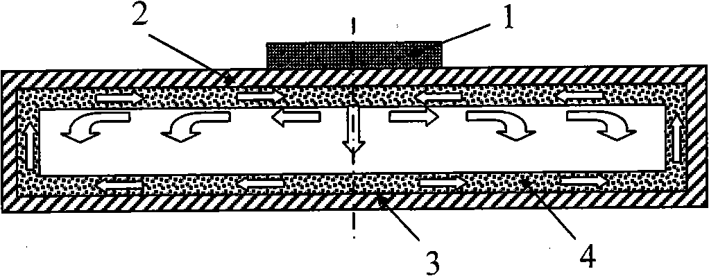
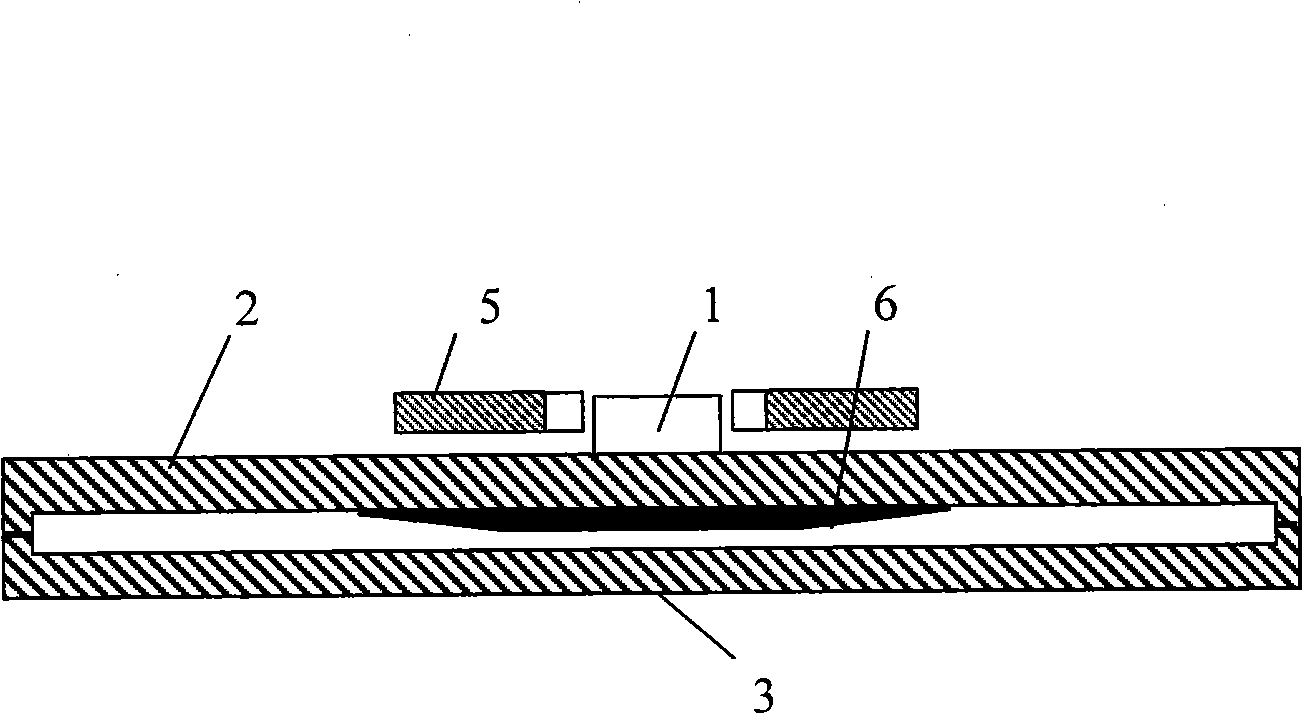
[0023] In this embodiment, the evaporating surface plate 2 and the condensing surface plate 3 are welded together. There is no capillary structure in the flat heat pipe cavity. After the flat heat pipe is evacuated, it is filled with magnetic fluid as a working fluid. A magnet 5 is arranged near the electronic device 1 outside the evaporation surface plate as an external magnetic field.

[0024] The specific structure diagram of the magnetic fluid flat heat pipe in this embodiment is as follows figure 2 shown. The diameter of the disc-shaped flat heat pipe is 85mm, and the material is red copper. The inner cavity height is 1 mm, and there is no capillary wick structure inside the cavity. The thicknesses of the evaporation surface plate 2 and the condensation surface plate 3 of the flat heat pipe are both 3 mm. An annular magnet 5 is placed outsid...


PUM


Abstract

The invention relates to a magnetic fluid flat heat pipe soaking machine that can be used as the soaking machine in an electronic apparatus cooling device. The invention aims to solve deficiency that a capillary core in the flat heat pipe soaking machine is hard to place and the capillary force is not enough. The whole magnetic fluid flat heat pipe is welded by an evaporate face flat (2) and a condensate flat (3). The flat heat cavity is provided with no any capillary structure. After extracting vacuum for the flat heat pipe, the flat heat pipe is filled with magnetic fluid as working substance. A magnet (5) is placed adjacent to an electronic apparatus (1) on an outer side of the evaporate face flat. The flat heat pipe can save design of the capillary liquid absorbing core. Placing additionally magnetic filed not only intensifies the working substance to boil, but also accelerates the working substance to flow back, which enables the magnetic fluid flat heat pipe to work under anti-gravity condition.

Description

technical field [0001] The invention relates to a heat spreader of a magnetic fluid flat plate heat pipe, which can be used as a heat spreader in a cooling device of an electronic device. Background technique [0002] The application of microelectronic chips pervades all aspects of daily life, production and even national security, and plays an extremely important role in modern civilization. The trend of chip development is to further increase integration, reduce chip size and increase clock frequency. The first chip produced by Intel in 1971 contained only 2,300 transistors, but today an Intel Pentium 4 chip has 42 million transistors integrated. A high level of integration is beneficial for upgrading computer performance. However, at the same time, the problems of chip energy consumption and heat dissipation have also emerged. With the rapid development of electronic technology, the high frequency and high speed of electronic devices and the density and miniaturization...

Claims


Application Information

Patent Timeline
Patent Type & Authority Applications(China)
IPC IPC(8): F28D15/02H05K7/20
Inventor 刘中良张明
Owner BEIJING UNIV OF TECH
Why Eureka
Try Eureka