

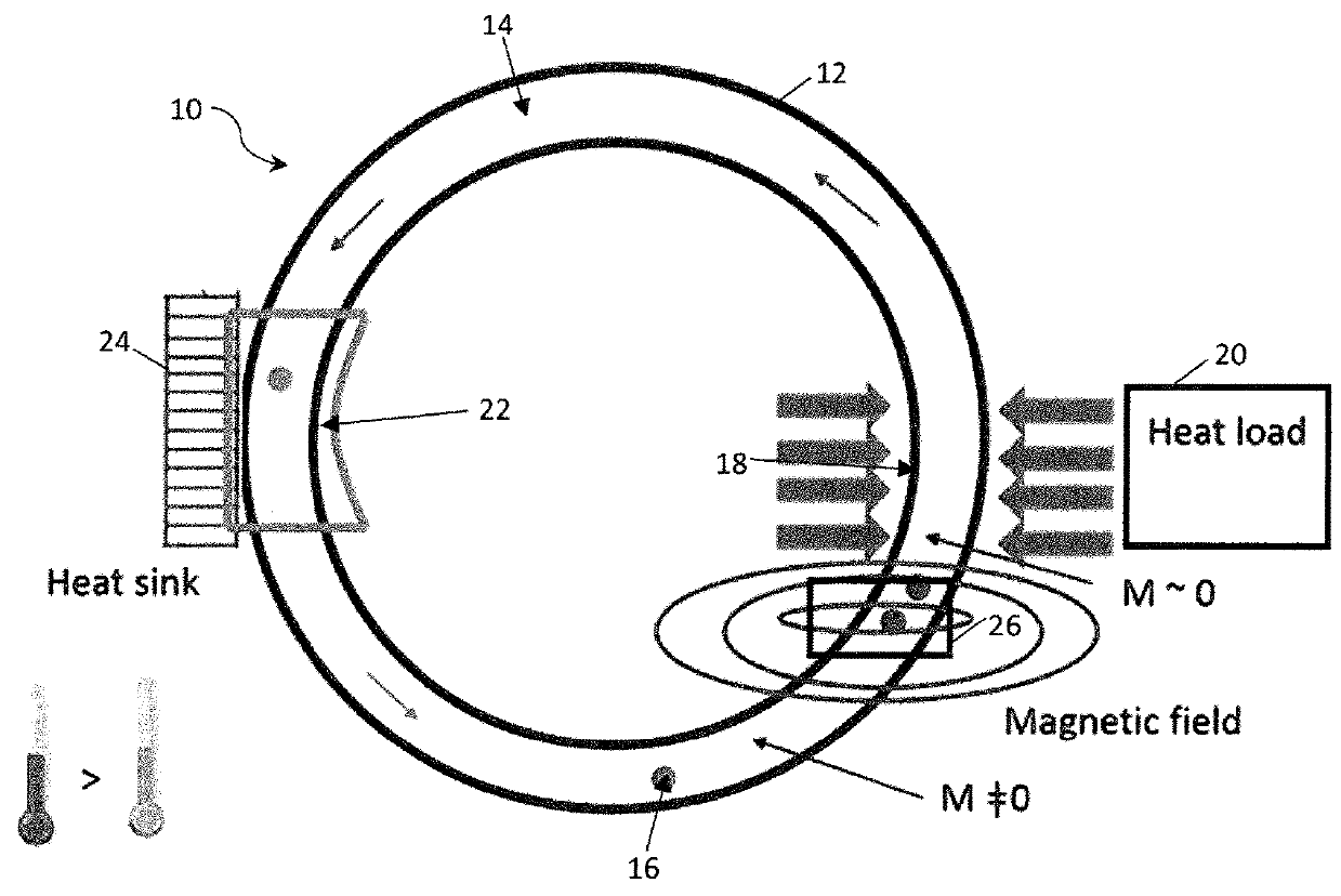
An apparatus for transferring heat from a heat source to a heat sink
- Summary
- Abstract
- Description
- Claims
- Application Information
AI Technical Summary
Benefits of technology
Problems solved by technology
Method used
Image

Examples
example 1
[0178]Six sample materials were prepared according to General Procedure 1. These materials were Fe70Ni30, (Fe70Ni30)99Cr1, (Fe70Ni30)97Cr3, (Fe70Ni30)95Cr5, (Fe70Ni30)94Cr6, and (Fe70Ni30)93Cr7, which will be referred to herein as Cr0, Cr1, Cr3, Cr5, Cr6 and Cr7, respectively. 70 wt % of iron and 30 wt % of nickel are used in Cr0. In Cr1, 1 wt % of chromium is added to 99 wt % of the 70:30 iron:nickel mixture and so on.
[0179]FIG. 16 shows the XRD patterns of Cr0, Cr1, Cr3, Cr5, Cr6 and Cr7 nanoparticles after heating at 700° C. for 2 h followed by quenching. All the samples exhibit three main diffraction peaks (111, 200 and 220) of the γ-FeNi phase with lattice parameter (a) in the range of 3.5919(4)-3.5983(3) Å and space group Fm-3m. Adding Cr to Fe70Ni30 does not shift in the diffraction peak positions much as the atomic radius of Cr does not differ much from the corresponding value for Fe and Ni. The average crystal sizes, calculated by the Scherrer formula after subtracting the ...
example 2
[0191]Fe—Ni—Cr nanoparticles were used to prepare the ferrofluid. (Fe70Ni30)95Cr5 nanoparticles were functionalized with oleic acid and ammonium hydroxide and subjected to high energy ball milling. Subsequently, these coated nanoparticles were dispersed in oleic acid.
[0192]Firstly, nanoparticles were synthesized by high energy ball milling in accordance with Example 1 to provide Cr0, Cr1, Cr3, Cr5, Cr6 and Cr7. The resulting nanoparticles were then subjected to further high energy ball milling under the same conditions for 10 hours in the presence of a mixture of oleic acid and ammonium hydroxide in a ratio of 8:2 wt:wt (oleic acid:hydroxide) in the milling vial. The ratio of nanoparticles to coating materials (oleic acid plus ammonium hydroxide) was around 5:1 wt:wt. The resulting coated product was then dispersed in oleic acid at a concentration of 2 vol %.
[0193]A ferrofluid of coated Fe—Ni—Cr nanoparticles and oleic acid as made above was then used as the heat transfer medium to ...
PUM
 Abstract
Description
Claims
Application Information