Power air-fuel levitation compression

Inactive Publication Date: 2008-02-19
ECONET INT CORP
View PDF11 Cites 6 Cited by
  • Summary
  • Abstract
  • Description
  • Claims
  • Application Information

AI Technical Summary

Benefits of technology

[0032]In a preferred embodiment, one or more magnets are applied to one or more of the fuel tank and fuel line of an internal combustion engine as close as possible to the carburetor or fuel injectors with only one pole of the magnet or magnets exposed to the fuel system. One or more magnets are applied to one or more of the air intake and air filter casing in such a way as to magnetically expose the intake air to the magnetic field emanating from the pole opposite that of the pole used to expose the fuel system. The fuel and air are thereby oppositely polarized or ionized, with the result that the fuel and combustion air exhibit a stronger attraction to each other with the consequence that there is more efficient and comp

Problems solved by technology

Smog is highly oxidizing in the environment and is the prime cause of eye and throat irritation, bad odor, plant damage, and decreased visibility.
Oxides of nitrogen are also toxic.
CO impairs blood capability to carry oxygen to the brain, resulting in slower reaction times and impaired judgment.
Motor vehicle manufacturers are constantly refining car designs to reduce their emissions of these pollutants, with many of these refineme

Method used


Image

  • Power air-fuel levitation compression
  • Power air-fuel levitation compression
  • Power air-fuel levitation compression

Examples


Embodiment Construction

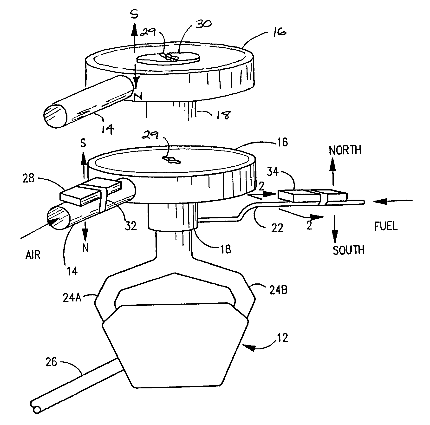
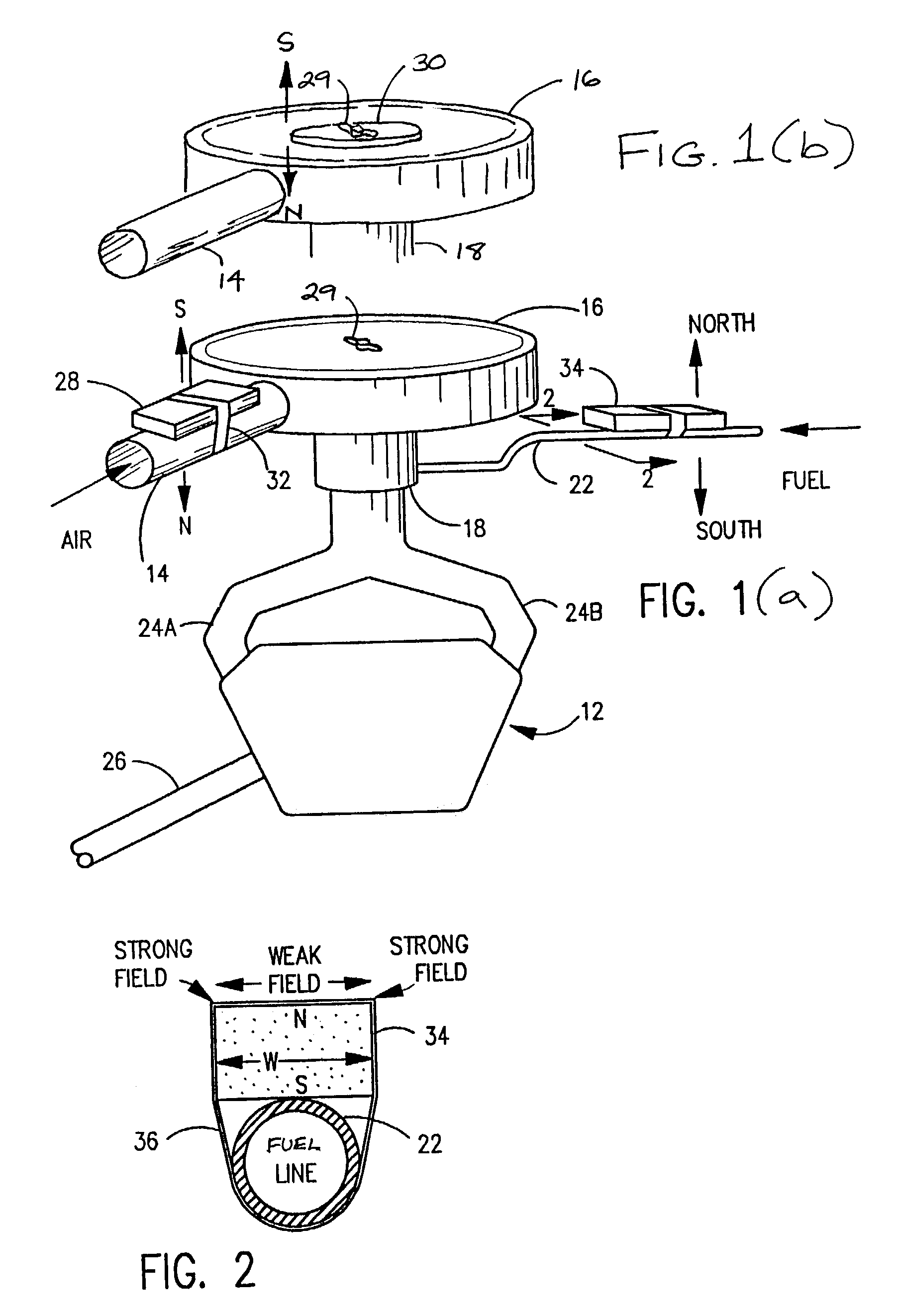
[0047]Referring now to FIG. 1(a), and in a preferred embodiment of the present invention, there is illustrated an internal combustion engine 12 provided with an air inlet manifold 14, an air filter 16, a carburetion or fuel injection device 18 hereinafter referred to as a carburetor, a fuel line 22 carrying a hydrocarbon liquid fuel to carburetor 18, and engine fuel-air mixture intake manifolds 24a and 24b. The products of combustion are discharged from engine 12 through an exhaust pipe 26. It will be apparent to one of ordinary skill in the relevant art of the invention that the present invention is amenable to incorporation in either a carburetor, where fuel is mixed with air prior to admission to the combustion chamber, as well as an injection system, where fuel is injected directly into the combustion air in the combustion chamber.

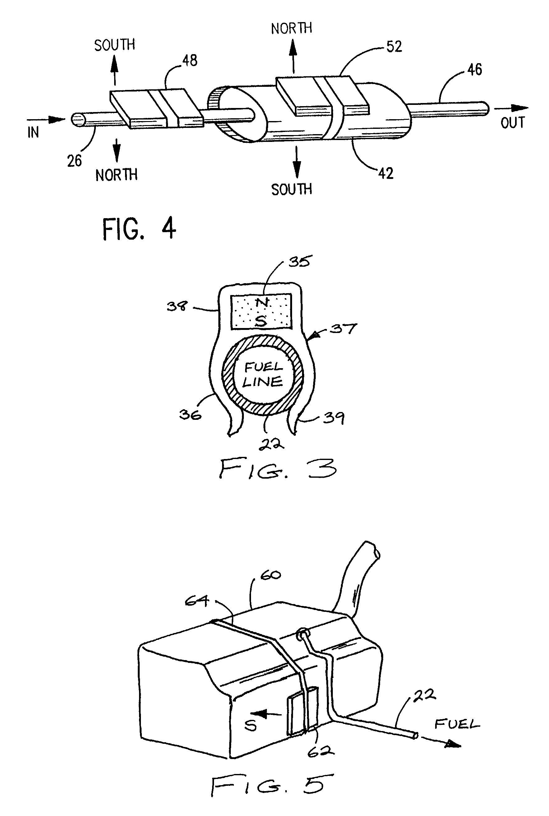
[0048]Magnetic fields are applied to the incoming air and the incoming fuel in the following manner. In one embodiment of the present invention, mount...


PUM


Abstract

Apparatus for magnetically conditioning incoming air and fuel to an internal combustion engine to improve engine operation. Magnets are applied in a bipolar arrangement to the fuel system and air intake apparatus of an internal combustion engine system for reducing emissions and improving fuel efficiency. Magnets may also be applied in a bipolar arrangement to the exhaust system and catalytic converter of an internal combustion system of automotive type for reducing exhaust emissions and improving the performance of a catalytic converter. Furthermore, a combination of magnetizing apparatus that, in conjunction with air and fuel magnetizing apparatus, will improve engine efficiency by introducing a magnetic charge to engine exhaust, coolant water, engine oil, transmission fluid, and gear box fluid, in combination with the above embodiment.

Description

CROSS REFERENCE TO RELATED APPLICATIONS[0001]This application is from provisional application Ser. No. 60 / 310,318 filed on Aug. 6, 2001, and provisional application Ser. No. 60 / 370,798 filed on Apr. 8, 2002, incorporated herein by reference.BACKGROUND OF THE INVENTION[0002]1. Field of the Invention[0003]The present invention relates to magnetic engine fluid conditioning systems, and in particular, to the incorporation of magnetic apparatus of a specific polarity to a combination of the fuel intake apparatus and air intake apparatus, the radiator inlet, the transmission housing, the gearbox housing, and the oil filter of an internal combustion engine system for the purpose of reducing emissions and improving fuel efficiency.[0004]2. Description of the Background[0005]There is a great scientific and regulatory interest in emissions from motor vehicles such as: (1) unburned hydrocarbons that are almost entirely intact or broken down components of the fuel, (2) carbon monoxide (CO) whic...

Claims


Application Information

Patent Timeline
IPC IPC(8): F02B75/10F01M11/03F02B3/06F02B51/04F02M27/04
CPCF02B51/04F02M27/045F01M2001/1042F02B3/06Y02T10/126Y02T10/12
Inventor RICHARD Z., HRICAK
Owner ECONET INT CORP
Why Eureka
Try Eureka