
Single power supply CMOS integrated circuit autosyn / rotary transformer - digital conversion technique
A resolver and self-aligning machine technology, applied in the direction of using electric/magnetic devices to transmit sensing components, etc., can solve the problems of large volume, high cost, and the inability to realize high-density installation of system components
- Summary
- Abstract
- Description
- Claims
- Application Information
AI Technical Summary
Problems solved by technology
Method used
Image

Examples
Embodiment 1
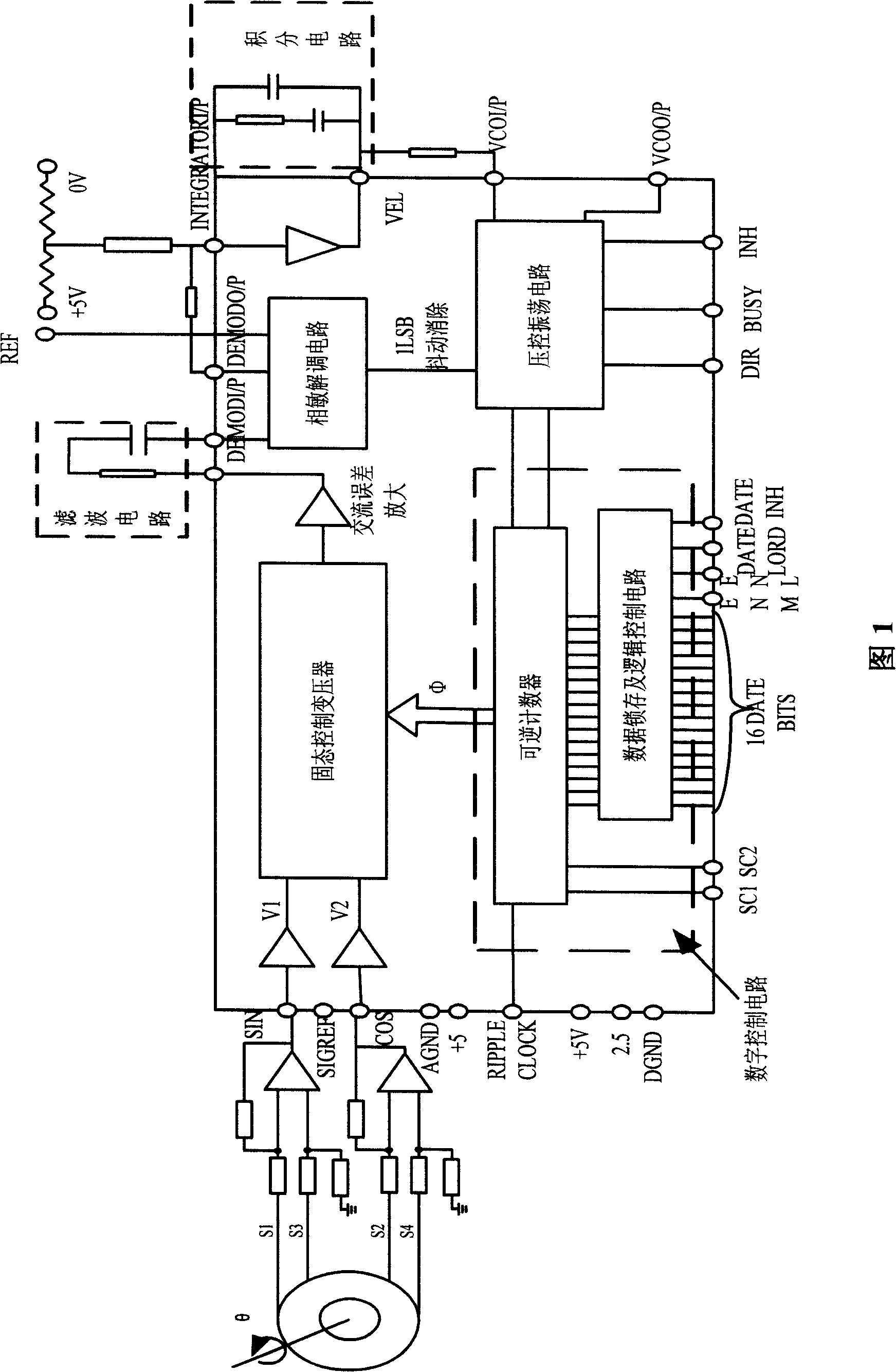
[0100] Example 1. A single-power supply CMOS integrated circuit synchro / resolver-to-digital conversion technology, which digitizes the synchro signal / resolver signal, converts the synchro signal / resolver signal into a binary digital signal, It consists of a solid-state control transformer circuit, an AC error amplifier circuit, a phase-sensitive demodulation circuit, an integral circuit, a voltage-controlled oscillation circuit and a digital control circuit; it adopts a standard CMOS integrated circuit process with a single power supply, and integrates the above circuits on a single chip , to achieve the conversion from angle to number.
Embodiment 2
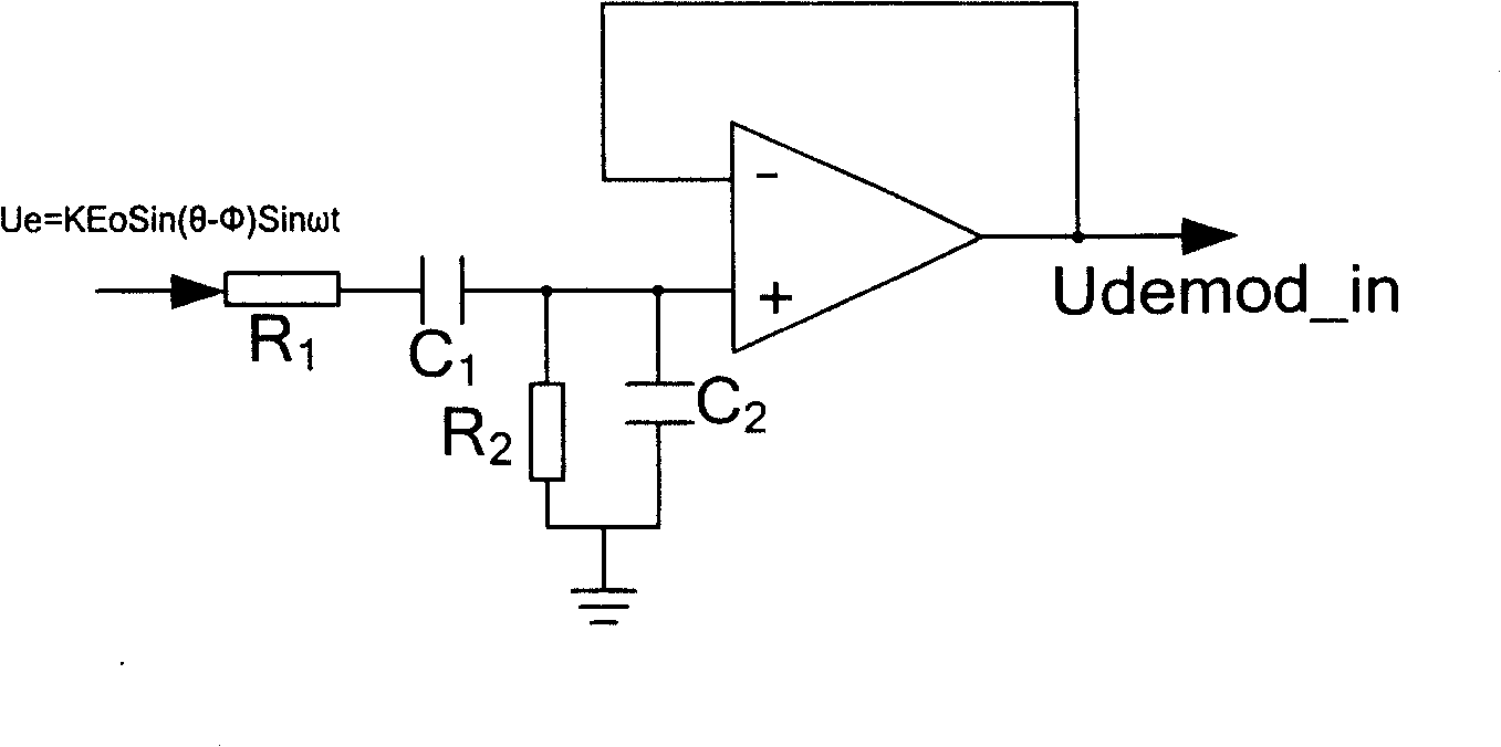
[0101] Example 2. In the conversion technology described in Embodiment 1, the three-wire input synthesizer signal or the four-wire input resolver signal is converted into low-voltage sine-cosine signals V1 and V2, and the digital angle φ generated by the reversible counter is controlled by the solid state. The summation in the transformer circuit outputs an error signal KEoSin(θ-φ) after passing through the AC error amplifier circuit. This error signal passes through a closed-loop circuit composed of a phase-sensitive demodulation circuit, an integrating circuit, a voltage-controlled oscillation circuit and a digital control circuit. Find the zero point of Sin(θ-φ); when this process is completed, the digital angle φ of the digital control circuit is equal to the signal input shaft angle θ.
Embodiment 3
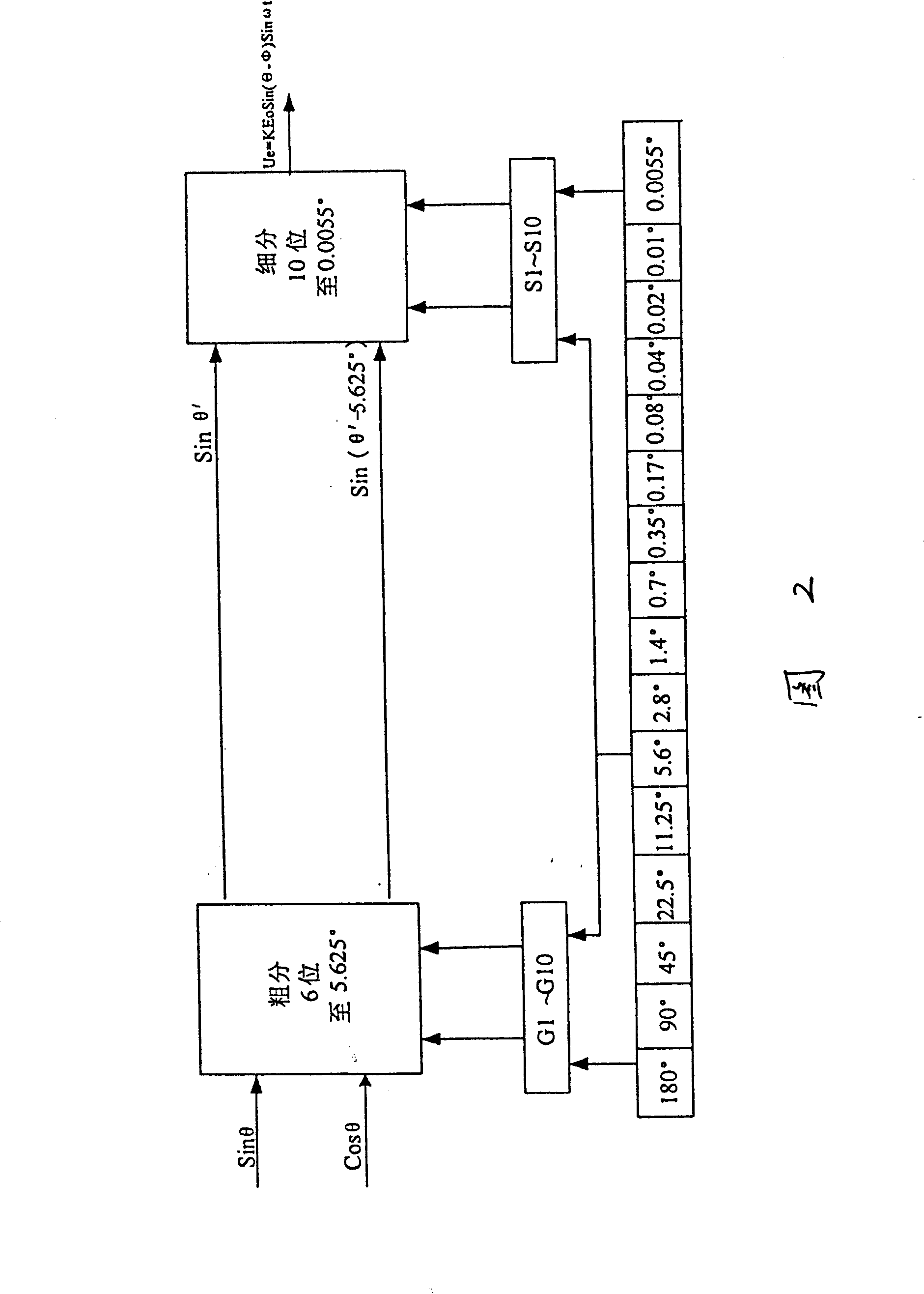
[0102] Example 3. In the conversion technology described in Embodiment 1, the solid-state control transformer circuit adopts a high 6-bit subdivision circuit and a low 10-bit subdivision circuit, and the high 6-bit subdivision circuit decomposes the angle variation 0°-360° to 0°-5.625 °, the lower 10-bit subdivision circuit uses a D / A converter with R-2R resistors to form an analog multiplier to realize the conversion from analog angle to digital angle within the range of 0°-5.625°.
PUM
 Abstract
Description
Claims
Application Information