Low differential voltage output circuit

A differential voltage and output circuit technology, applied in the direction of differential amplifiers, DC-coupled DC amplifiers, etc., can solve the problems of limited response time of the type transmission interface, large and complex circuit scale, and increased cost.

Inactive Publication Date: 2008-10-08
NOVATEK MICROELECTRONICS CORP
View PDF0 Cites 8 Cited by
  • Summary
  • Abstract
  • Description
  • Claims
  • Application Information

AI Technical Summary

Problems solved by technology

However, since the differential output unit must be controlled by the feedback circuit 130, the response time of this type of transmission interface is limited, and its optimal conditions will also drift due to process variations.
[0006] In addition, because a general chip contains multiple sets of differential output units, and each differential output unit needs to be equipped with a feedback circuit for feedback control, resulting in a substantial increase in cost
From the above disadvantages, it can also be imagined that when the system needs to transmit more differential signals, the circuit scale will become quite complex

Method used


Image

  • Low differential voltage output circuit
  • Low differential voltage output circuit
  • Low differential voltage output circuit

Examples


Embodiment Construction

[0059] In order to facilitate the comparison between the diagrams, the power supply voltage and common potential in the following diagrams are represented by VCC and COM respectively.

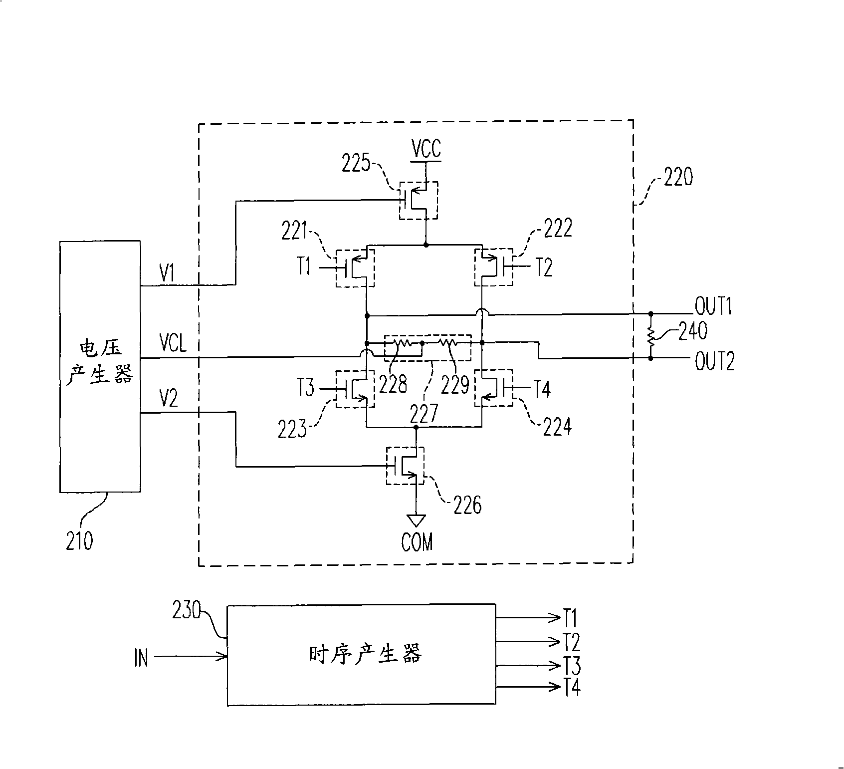
[0060] Please refer to figure 2 , figure 2 It is a circuit diagram of a low differential voltage output circuit according to an embodiment of the present invention. The low differential voltage output circuit includes a voltage generator 210 and a differential output unit 220 , wherein the differential output unit 220 is composed of switches 221 - 224 , controlled current sources 225 - 226 and a common-mode voltage circuit 227 .

[0061] The voltage generator 210 is used to generate the bias voltages V1, V2 and the clamping voltage VCL. The controlled current source 225 clamps the value of the current provided by it to the first preset range according to the bias voltage V1, and the controlled current source 226 according to the bias voltage V2 clamps the value of the current it provides wi...


PUM


Abstract

A low differential voltage output circuit comprises a voltage generator and a differential output unit. The voltage generator comproses a first PMOS transistor, a first amplifier circuit, a unity gain stage, a first and s second NMOS transistors. The differential output unit comprises a first controlled current source, a second controlled current source, a common mode voltage circuit and a first, a second, a third and a fourth switches. The invention directly provides the common mode voltage to the differential output unit by the voltage generator, overcomes channel modulation effect of the MOS transistor and increases driving force of the common mode voltage, so the reactive time of the invention changes small, the output current of the differential output unit is in proportion with the reference current received by the voltage generator, and only one voltage generator can meanwhile connect with a plurality of differential output units in series.

Description

technical field [0001] The invention relates to an output circuit, in particular to a low differential voltage output circuit. Background technique [0002] In recent years, electronic products have developed more diversified. In order to enable communication between electronic products, integrated circuits, or functional modules in integrated circuits, so as to optimize the functions of each product, each A transmission interface also came into being. [0003] In order to reduce electromagnetic interference (EMI) and power consumption, most of these transmission interfaces are designed as differential outputs, such as figure 1 The differential output circuit in is shown. figure 1 It is a schematic diagram of an existing differential output circuit and its arrangement position. Please refer to figure 1 , the differential output circuit is set inside the chip, and the circuit includes a differential output unit composed of MOS (metal-oxide-semiconductor) transistors 102 -...

Claims


Application Information

Patent Timeline
IPC IPC(8): H03F3/45
Inventor 黄俊乂
Owner NOVATEK MICROELECTRONICS CORP
Why Eureka
Try Eureka