
Simple fold line scaling supersonic nozzle for numerical control laser cutting

A technology of supersonic nozzle and numerical control laser, which is applied in laser welding equipment, welding equipment, metal processing equipment, etc., can solve the problems of complex curve of nozzle inner wall, increase of gas turbulence, and decrease of effective cutting area, etc. CNC cutting accuracy and cutting efficiency, easy processing and manufacturing, uniform and tidy effect

Inactive Publication Date: 2008-10-15
SHANGHAI JIAO TONG UNIV
View PDF2 Cites 8 Cited by
  • Summary
  • Abstract
  • Description
  • Claims
  • Application Information

AI Technical Summary

Problems solved by technology

[0003] At present, converging nozzles are widely used in cutting production. Although they are simple in structure and easy to process, when cutting medium and thick plates with high-pressure gas, shock waves will occur in the gas near the incision, which seriously deteriorates the quality of the outlet gas. Dynamic performance, the turbulence of the gas increases, the flow field structure is very sensitive to the change of the distance between the nozzle and the workpiece, the effective cutting area is significantly reduced, and the cutting efficiency and cutting quality are reduced
[0004] After searching the literature of the prior art, it was found that the Chinese patent application No. CN200510095474.X "a new type of laser cutting head" and the application No. CN200710044903.X "supersonic nozzle for laser cutting" found that for supersonic For the design of the most important expansion section of the nozzle, the former adopts Foelsch streamline fitting, and the latter adopts the high-order curve fitting of the simplified Hall design method. The curves of the inner wall of the nozzle are very complicated and difficult to manufacture

Method used


Image

  • Simple fold line scaling supersonic nozzle for numerical control laser cutting
  • Simple fold line scaling supersonic nozzle for numerical control laser cutting
  • Simple fold line scaling supersonic nozzle for numerical control laser cutting

Examples


Embodiment Construction

[0016] The embodiments of the present invention will be described in detail below with reference to the drawings: this embodiment is implemented on the premise of the technical solution of the present invention, and detailed implementation modes and specific operation procedures are given, but the protection scope of the present invention is not limited to the following Mentioned examples.

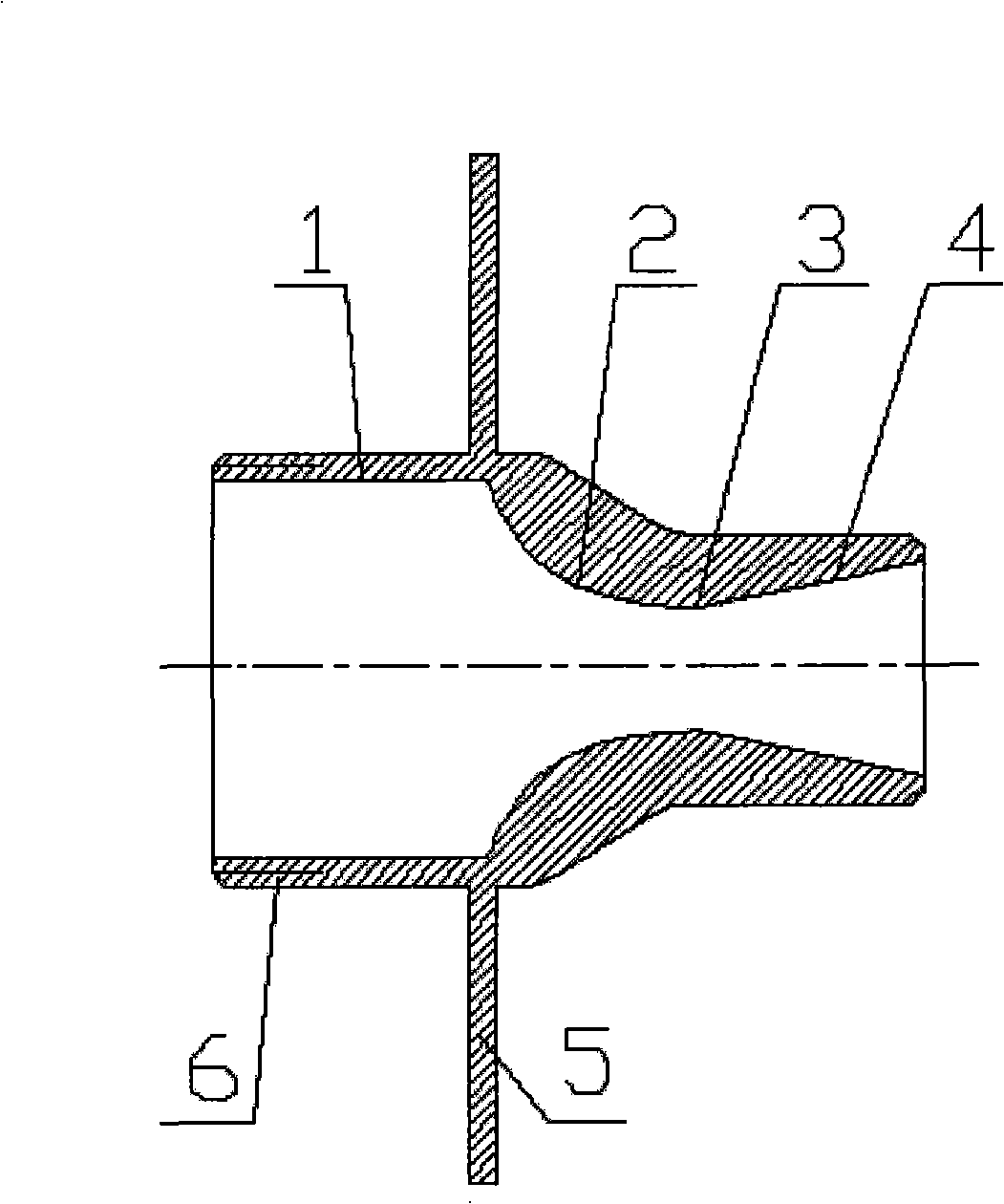
[0017] Such as figure 1 As shown, this embodiment includes: a parallel section 1, a contraction section 2, a throat 3, and an expansion section 4, which are constituted as a connected whole. The inlet of the parallel section 1 is connected to the laser gas cavity to store high-pressure auxiliary gas, the outlet of the parallel section 1 is connected to the inlet of the contraction section 2, the outlet of the contraction section 2 is connected to the left side of the throat 3, and the right side of the throat 3 is connected to the expansion section 4 and the throat 3 The design is used to rea...


PUM


Abstract

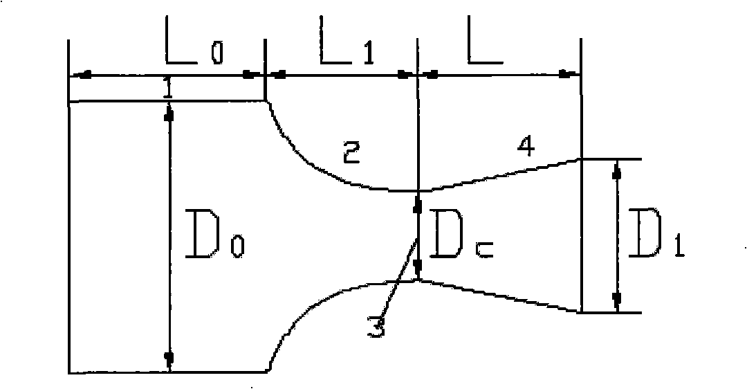
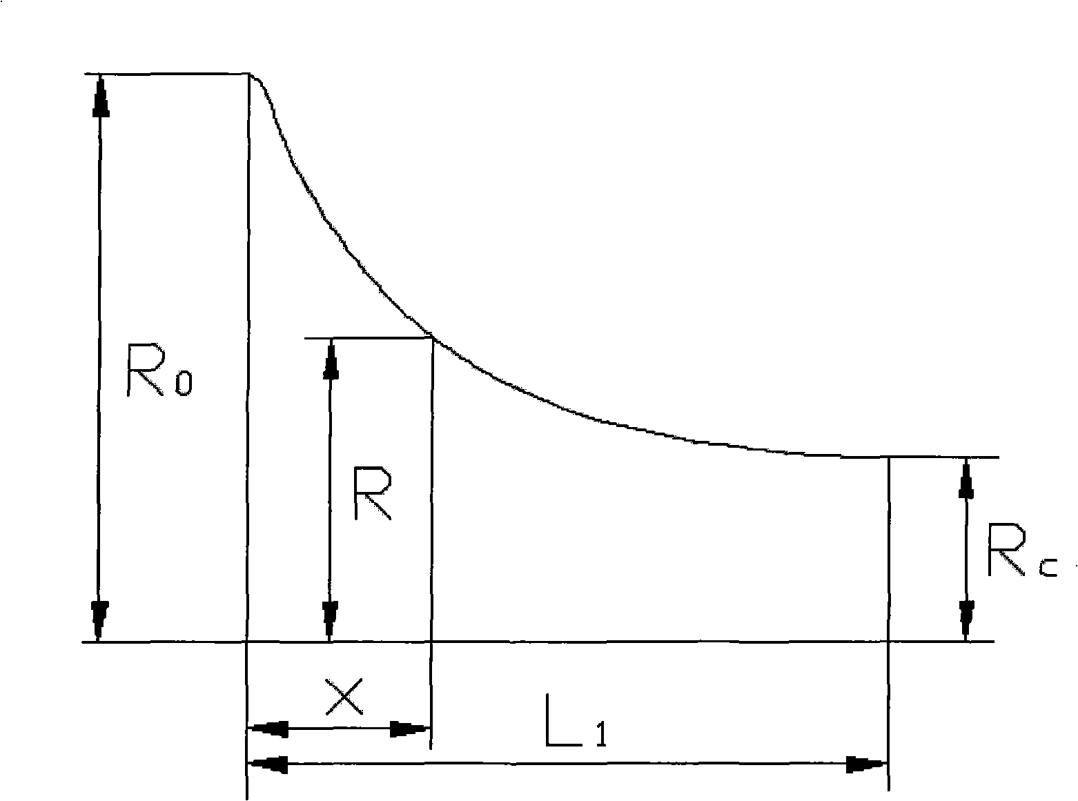
The invention relates to a simple broken-line scaling supersonic nozzle used for digital controlled laser cutting, which comprises a parallel segment, a shrinkage segment, a throat part and an extension segment. The extension part is a straight line segment; the ratio between the entry radius R0 of the shrinkage segment and the radius Rc of the throat part is determined by the entry mach number M0 of the shrinkage segment, the mach number Mc of the throat part and an aerothermodynamic factor K; the ratio between the exit radius R1 of the extension segment and the radius Rc of the throat part is determined by the exit mach number M1 of the extension segment, the mach number Mc of the throat part and the aerothermodynamic factor K; when R0 / Rc is equal to a constant, and R1 / Rc is equal to a constant, the exit mach number of the supersonic nozzle is kept as a fixed value under the action of gas pressure. When the supersonic nozzle conducts digital controlled laser cutting, the air stream sprayed from the nozzle is uniform, and the mass flow rate and the momentum are large, thereby effectively blowing off molten metal and other slag. Furthermore, the cut is narrow and tidy, without adhering slag staying on the edge of cutting seam, and the cutting quality and efficiency are obviously improved.

Description

Technical field [0001] The invention relates to a nozzle in the technical field of numerical control laser cutting, in particular to a simple fold line zoom supersonic nozzle for numerical control laser cutting. Background technique [0002] In the process of CNC laser cutting, the nozzle is one of the key parts of laser cutting, used as a common channel for high-energy laser beam and auxiliary gas. During the laser cutting process, the auxiliary gas blows the molten metal from the slit on the one hand, and on the other hand allows the metal near the slit to be rapidly cooled, thereby reducing slagging and reducing the heat-affected zone. Therefore, a good nozzle design can not only effectively ensure the cutting quality, but also greatly improve the cutting efficiency. [0003] At present, convergent nozzles are widely used in cutting production. Although they are simple in structure and easy to process, when high-pressure gas is used to cut medium and thick plates, shock waves ...

Claims


Application Information

Patent Timeline
Patent Type & Authority Applications(China)
IPC IPC(8): B23K26/00B23K26/38B23K26/14
Inventor 胡俊邱明勇盛晓军刘放
Owner SHANGHAI JIAO TONG UNIV
Learn More