Thermal water utilization device and steam treatment device

A hot water and steam technology, which is applied in the fields of hot water utilization devices and steam treatment equipment, can solve the problem of not realizing the effective utilization of hot water, and achieve the effect of effective utilization

Inactive Publication Date: 2008-10-15
KOBE STEEL LTD
View PDF1 Cites 5 Cited by
  • Summary
  • Abstract
  • Description
  • Claims
  • Application Information

AI Technical Summary

Problems solved by technology

[0003] In the above-mentioned equipment, the condensed water generated in the flash tank 93 is guided to the discharge container 9

Method used


Image

  • Thermal water utilization device and steam treatment device
  • Thermal water utilization device and steam treatment device

Examples


Embodiment Construction

[0016] Hereinafter, the best mode for carrying out the present invention will be described in detail with reference to the drawings.

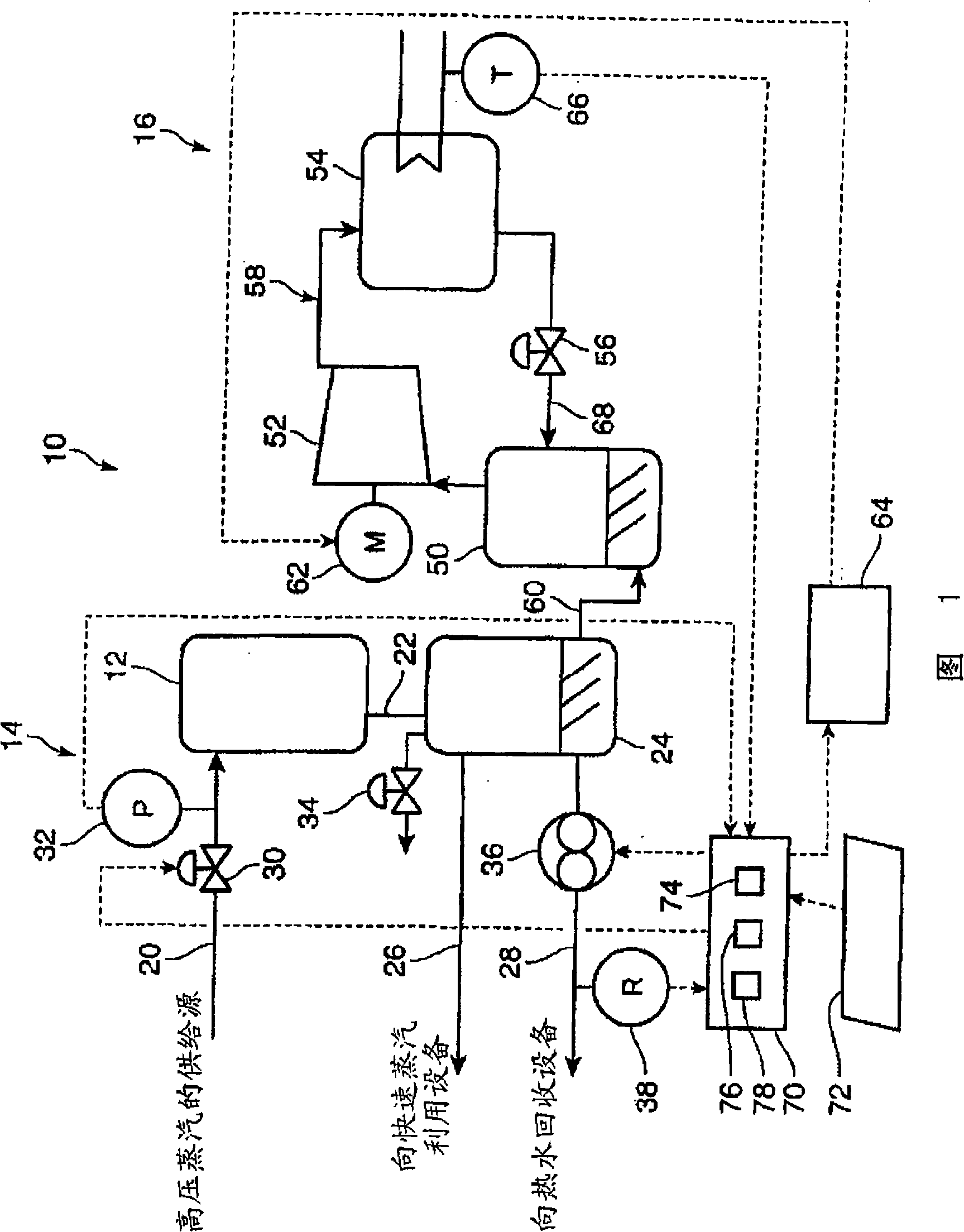
[0017] FIG. 1 schematically shows the configuration of a steam treatment facility using an embodiment of the hot water utilization device of the present invention. As shown in the figure, this steam processing facility 10 has a steam utilization system 14 having a process facility 12 for utilizing heat obtained from steam, and a hot water utilization device 16 attached to the steam utilization system 14 .

[0018] The steam utilization system 14 has a supply line 20 connected to a supply source of high-pressure steam, a process equipment 12 arranged at the downstream end of the supply line 20, a flash tank 24 connected to the process equipment 12 via a connection line 22, and the flash tank 24. The steam recovery line 26 and the hot water recovery line 28 are connected to the tank 24 . In the supply line 20 , high-pressure steam having a prede...


PUM


Abstract

The invention relates to a hot water utilizing device and a steam processing equipment; the hot water utilizing device has a hot water container connected with a flash tank and leading in the hot water from the flash tank, a compressing mechanism for absorbing the steal in the hot water container and compressing the same, a heat exchanger for providing the heat of the steam compressed by the compressing mechanism to the exterior utilized heat medium, an expansion valve for expanding the hot water through the heat exchanger and a capacity control mechanism for controlling the capacity of the compressing mechanism according to the test value of the temperature sensor. The rest hot water not utilized by the hot water recovering equipment is led in the hot water container. Through the structure, the amount of the condensed water discharged from the flash tank is reduced as possible; and the invention is bale to realize the effect utilization of the steam and condensed water.

Description

technical field [0001] The present invention relates to a hot water utilization device and steam processing equipment used in connection with a temporary storage container for storing hot water. Background technique [0002] Conventionally, various systems are known for steam processing facilities utilizing heat obtained from steam. For example, Japanese Patent Application Laid-Open No. 8-189307 discloses a gas turbine complex including a gas turbine 94 and an exhaust heat recovery boiler 91 as shown in FIG. 2 . In this facility, a flash tank 93 is provided to generate steam from the drain of the steam drum 92 of the flash exhaust heat recovery boiler 91, and the steam generated in the flash tank 93 is injected into the combustor 95 of the gas turbine 94. Work is performed in the gas turbine 94 to increase the output of the gas turbine 94 . [0003] In the above equipment, the condensed water generated in the flash tank 93 is guided to the discharge container 97, is not ef...

Claims


Application Information

Patent Timeline
IPC IPC(8): F22B37/34F22D7/00
CPCY02A30/274
Inventor 松隈正树松井孝益上原一浩胁田高行
Owner KOBE STEEL LTD
Why Eureka
Try Eureka