
All-digital compensation microwave radiometer

A microwave radiometer, all-digital technology, applied in the field of guidance and precision measurement, microwave remote sensing, can solve the problems affecting the accuracy of measurement, large measurement error, complex circuit structure, etc., to achieve improved stability, improved efficiency, and light weight Effect

Inactive Publication Date: 2008-10-15
HUAZHONG UNIV OF SCI & TECH
View PDF0 Cites 16 Cited by
  • Summary
  • Abstract
  • Description
  • Claims
  • Application Information

AI Technical Summary

Problems solved by technology

In this derivation it is assumed that the receiver noise T REC is stable, but in actual use, due to noise fluctuations in the system and changes in the reference source, this compensation method will inevitably cause measurement errors, thereby affecting the accuracy of the measurement
However, the real-time calibration microwave radiometer uses two radio frequency switches and two microwave reference sources, which increases the complexity of the device and thus introduces additional errors
[0005] The above radiometers have achieved certain effects in reducing or eliminating the influence of system gain fluctuations and local noise, but they either use dual reference sources, or use synchronous demodulation and negative feedback loops, and at the same time adjust the system gain through AGC Or use dual reference sources to eliminate system gain and local noise fluctuations, which have a great impact on the measurement accuracy of the radiometer and system stability; at the same time, the circuit structure is complex, which brings difficulties to the long-term use of the radiometer; The multiple assumptions made in the derivation will bring a lot of error to the measurement
Therefore, problems such as the elimination of system gain and the influence of local noise fluctuations, the selection of reference noise sources, the calculation of radiation brightness temperature, and temperature detection are all problems that cannot be well resolved in the development of radiometers.
At the same time, these radiometers need to be calibrated periodically, which not only has a complicated calibration structure, but also brings large measurement errors, which brings difficulties to the long-term use of the radiometer.

Method used


Image

  • All-digital compensation microwave radiometer
  • All-digital compensation microwave radiometer
  • All-digital compensation microwave radiometer

Examples


example

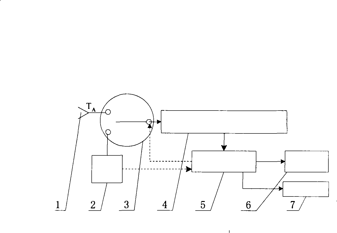
[0051] Developed a full digital compensation 8mm radiometer, the radiometer mainly uses the following components:

[0052] 1. Antenna 1 uses an 8mm pyramidal horn antenna, and the antenna diameter is 8cm*4cm;

[0053] 2. The microwave switch 3 is a knot-type lock-type waveguide switch produced by the Second Academy of Aerospace Science and Technology. The switch is equivalent to a single-pole double-throw microwave switch with good switching stability and low forward insertion loss.

[0054] 3. Matching load 2 adopts the matching load produced by Beijing Dahua Company, and the VSWR is 1.05;

[0055] 4. The full-power radiometer 4 adopts the integrated structure type produced by the former Russian Saturn Company, the working frequency f=35GHz, the intermediate frequency bandwidth Δf≈1GHz; the front-end gain G=65dB; the double-sided band noise factor F=6dB.

[0056] 5. The data acquisition and control unit 5 is the core component of the all-digital compensation microwave radio...


PUM


Abstract

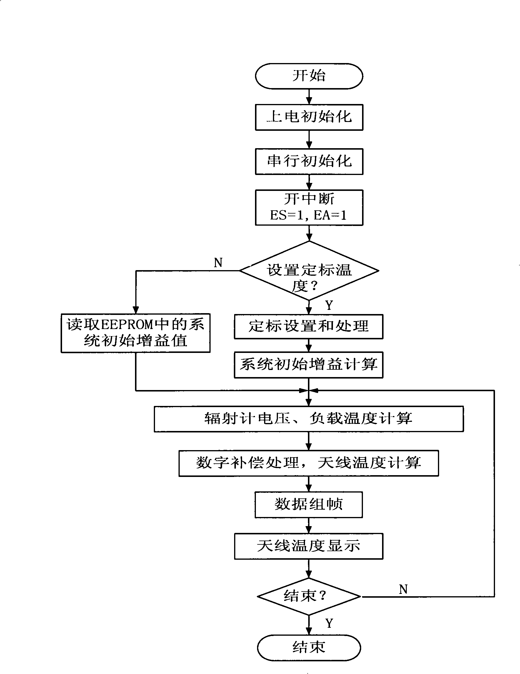
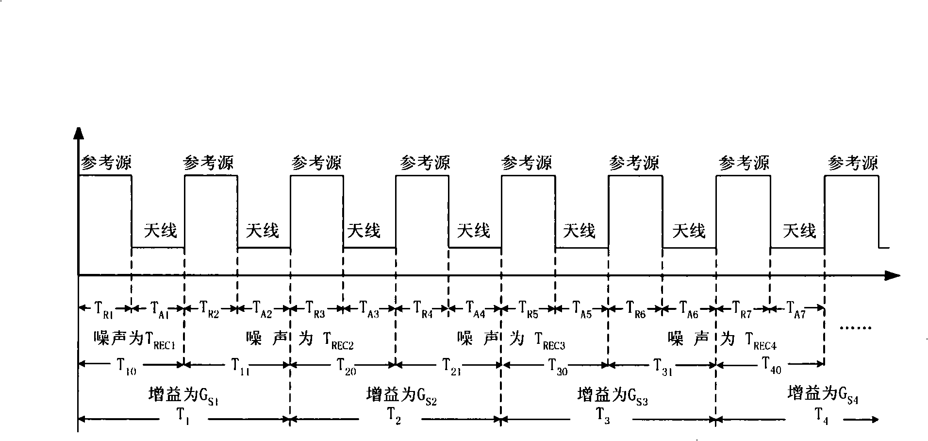
The invention discloses an all-digital compensation microwave radiometer, which comprises an antenna, a matched load, a microwave switch, a full-power radiometer, a digital control unit, a communication unit and a display unit. According to the cycle detection of the input voltage of the matched antenna and the antenna and the practical temperature of the matched load, the influence on the performance of the radiometer caused by the gain uncertainty of a radiometer system and local noise fluctuation is balanced out through the digital compensation operator of the digital control unit. The all-digital compensation microwave radiometer not only greatly increases sensitivity and long-term stability, but also has simple structure and small volume; moreover, the radiometer can work for a long time after initial calibration, thereby avoiding the inconvenience of cycle calibration on ground basis, vacuous basis and satellite basis and greatly increasing target observation time and scope.

Description

technical field [0001] The invention belongs to the technical field of microwave remote sensing, guidance and precision measurement, and in particular relates to an all-digital compensation microwave radiometer. Background technique [0002] Microwave radiometer is the core equipment of passive microwave remote sensing and the only tool for detecting, imaging and judging the microwave radiation characteristics of ground object background and target. [0003] The development trend of microwave radiometer is from graphic to imaging radiometer, from low resolution radiometer to high resolution radiometer. Usually microwave radiometer output fluctuations are determined by the local noise uncertainty ΔT N 2 and the system gain uncertainty ΔT G 2 It was determined that in order to reduce the influence of system gain instability and local noise fluctuation on the output of the radiometer, various methods have been adopted and different types of radiometers have been developed. ...

Claims


Application Information

Patent Timeline
IPC IPC(8): G01R29/08G01J5/00
Inventor 桂良启郎量陈柯黄全亮郭伟张祖荫
Owner HUAZHONG UNIV OF SCI & TECH
Learn More