Heat-resistant component with heat insulation coating
A technology of covering layer and heat insulation layer, which is applied in the direction of plating of superimposed layers, supporting elements of blades, coating, etc., can solve the problems of reduced mechanical properties of heat-resistant alloy matrix materials, low strength of metamorphic layers, etc., and achieve reliability Excellent, sufficient durability, and the effect of realizing high temperature
- Summary
- Abstract
- Description
- Claims
- Application Information
AI Technical Summary
Problems solved by technology
Method used
Image
Examples
Embodiment 1
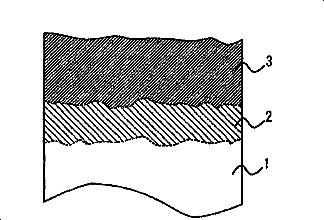
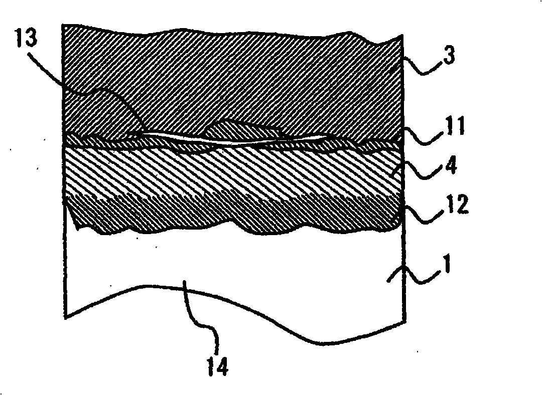
[0075] As the test piece base material, a disc-shaped Ni-based heat-resistant alloy with a diameter of 25 mm and a thickness of 5 mm (by weight, C: 0.03% to 0.20%, B: 0.004% to 0.050%, Hf: 0.01% to 1.50% % or less, Zr: 0% to 0.02%, Cr: 1.5% to 16.0%, Mo: 0.4% to 6.0%, W: 2% to 12%, Re: 0.1% to 9.0%, Ta: 2% to 12%, Nb: 0.3% to 4.0%, Al: 4.0% to 6.5%, Ti: 0% to 0.4%, Co: 0.5% to 9.0%, and the rest are basically Ni; Specifically, by weight, C: 0.11%, B: 0.025%, Hf: 0.75%, Zr: 0.01%, Cr: 7.5%, Mo: 2.8%, W: 6%, Re: 4.5%, Ta: 6.5%, Nb: 2.1%, Al: 5.2%, Ti: 0.2%, Co: 4.5% and the rest are basically single crystal materials of Ni), using NiCrAl alloy (Ni-22wt%Cr-10wt% The Al) powder was formed into a bonding layer by plasma spraying in a reduced-pressure atmosphere, and a heat treatment at 1121° C. for 4 hours in vacuum was performed as a diffusion heat treatment.
[0076] The thickness of the bonding layer is about 100 μm. Then, yttria is used to partially stabilize zirconia (ZrO ...
Embodiment 2
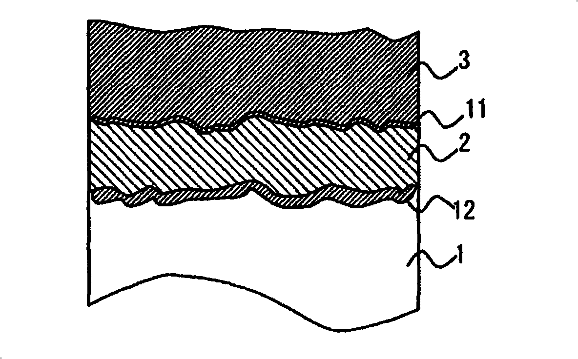
[0084] Using the same test piece base material as in Example 1, use the NiCrAl alloy (Ni-22wt%Cr-10wt%Al) powder and NiCrAlSi alloy (Ni-22wt%Cr-10wt%Al-1wt%Al) powder of the present embodiment on its surface %Si) powder, form a bonding layer by plasma spraying in a reduced-pressure atmosphere, and perform a heat treatment at 1121° C. for 4 hours in vacuum as a diffusion heat treatment.
[0085]The thickness of the bonding layer is about 100 μm. Then, the following four methods are used to form yttria partially stabilized zirconia (ZrO 2 -8wt%Y 2 o 3 ) insulation layer.
[0086] The first method is to form a heat insulating layer with a porosity of about 10% by plasma spraying in the atmosphere.
[0087] The second method is to form a porous heat insulating layer with a porosity of about 20% by plasma spraying in the atmosphere.
[0088] The third method: form a heat insulating layer with longitudinal cracks by plasma spraying in the atmosphere.
[0089] The fourth method...
Embodiment 3
[0102] A rotor blade of a gas turbine equipped with a TBC according to the present embodiment was produced. Figure 4 A perspective view showing the overall structure of a rotor blade of a gas turbine is shown.
[0103] Figure 4 In this gas turbine, the rotor blade is a single crystal material of a Ni-based heat-resistant alloy (the composition of which is the same as that shown in Example 1), for example, as the primary Rotating blades are used, having a blade part 61 , a platform part 62 , a body part 63 , sealing tabs 64 , chip pockets 65 , mounted on a disc by means of dovetail slots 66 .
[0104] In addition, the blade portion 61 of the rotor blade of the gas turbine has a length of 100 mm, and the length below the platform portion 42 is 120 mm. The gas turbine rotor blade is passed through a refrigerant for cooling from the inside, especially for allowing air or water vapor to pass through. Cooling holes (not shown) leading from the dovetail groove 66 to the blade por...
PUM
| Property | Measurement | Unit |
|---|---|---|
| thickness | aaaaa | aaaaa |
| thickness | aaaaa | aaaaa |
| length | aaaaa | aaaaa |
Abstract
Description
Claims
Application Information
 - R&D
- Intellectual Property
- Life Sciences
- Materials
- Tech Scout
- Unparalleled Data Quality
- Higher Quality Content
- 60% Fewer Hallucinations
Browse by: Latest US Patents, China's latest patents, Technical Efficacy Thesaurus, Application Domain, Technology Topic, Popular Technical Reports.
© 2025 PatSnap. All rights reserved.Legal|Privacy policy|Modern Slavery Act Transparency Statement|Sitemap|About US| Contact US: help@patsnap.com


