

Filth-resisting thin film
A thin film and fouling layer technology, applied in antifouling/underwater coatings, coatings, instruments, etc., can solve problems such as undisclosed protective films
- Summary
- Abstract
- Description
- Claims
- Application Information
AI Technical Summary
Problems solved by technology
Method used
Image

Examples
preparation example Construction
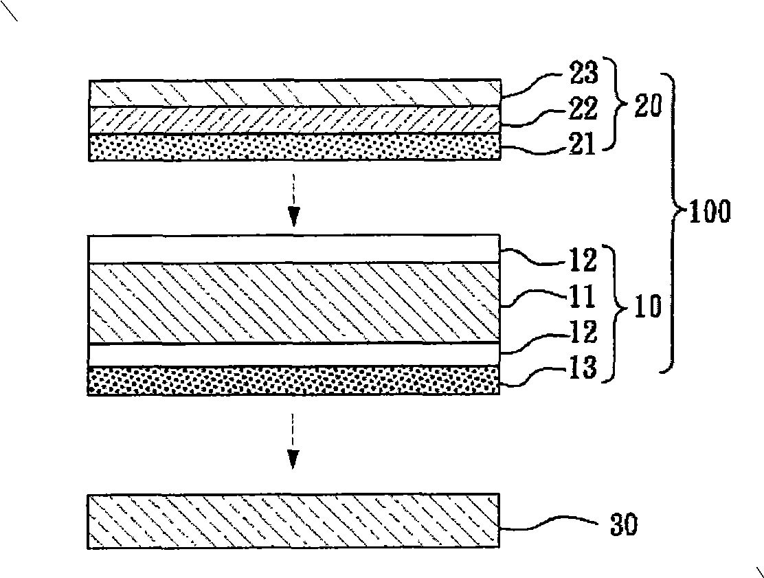
[0047] The preparation method of the antifouling film of the present invention is not particularly limited, for example, it can be produced by a coating method comprising the following steps:
[0048] (1) The coating composition prepared by blending components such as polyfluorosiloxane acrylic comb-type graft copolymer and antistatic agent (if necessary, other known additives can be added and diluted with solvent) is formulated into Coating solution;
[0049] (II) coating the coating solution on the surface of the substrate through a wire rod coating rod to form an antifouling layer;
[0050] (III) Sending the coated substrate into a dryer, heating at a suitable temperature for several minutes, evaporating the solvent, and performing thermal curing polymerization.
[0051] The solvent system described in the above step (I) is not particularly limited, for example, it may be benzene, ester or ketone or a mixture thereof. Non-limiting examples of benzene-based solvents includ...
Embodiment 1
[0058] Get 1 part by weight of polyfluorosiloxane acrylic acid-based comb-type graft copolymer [E-4263, Eternal Company] (about 55% of solid content), the main chain of the copolymer is an acrylic polymer, branched The chain part is composed of 2% fluorinated acrylic monomer and 3% siloxane monomer, the molecular weight is 20000~30000, adding 0.3 parts by weight of isocyanate crosslinking agent [Desmodur 3390, Bayer company] (solid content About 75%), then add 3 parts by weight of quaternary ammonium salt antistatic agent [GMB-36M-AS, Marubishi oil Chem.Co., Ltd] (solid content about 20%) to form a coating composition, finally use propylene glycol methyl Dilute with ether, ethyl acetate, toluene and other solvents to obtain a coating with a solid content of about 2.5% and a viscosity of less than 10 cps. After standing for defoaming, apply the prepared coating on a polyethylene terephthalate (PET) film [T100G-38, Mitsubishi Chem.Co.] (thickness 38 μm) through a wire rod coatin...
Embodiment 2
[0061] Use the coating composition and method of embodiment 1 to prepare antifouling film, but change the solid coating amount of antifouling layer to 75mg / m 2 .
PUM
| Property | Measurement | Unit |
|---|---|---|
| thickness | aaaaa | aaaaa |
Abstract
Description
Claims
Application Information