Circuit arrangement having a free-wheel diode

A freewheeling diode and circuit device technology, applied in the direction of diodes, circuits, electrical components, etc., can solve the problem of high surge tolerance and achieve the effect of reducing noise

Inactive Publication Date: 2008-10-22
HITACHI LTD
View PDF1 Cites 13 Cited by
  • Summary
  • Abstract
  • Description
  • Claims
  • Application Information

AI Technical Summary

Problems solved by technology

In addition, since a large current can flow, the tolerance to surge is also high

Method used


Image

  • Circuit arrangement having a free-wheel diode
  • Circuit arrangement having a free-wheel diode
  • Circuit arrangement having a free-wheel diode

Examples


Embodiment Construction

[0056] Hereinafter, embodiments of the present invention will be described using the drawings.

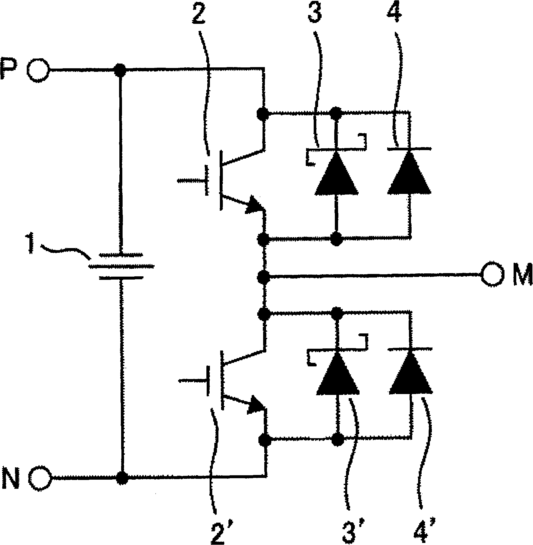
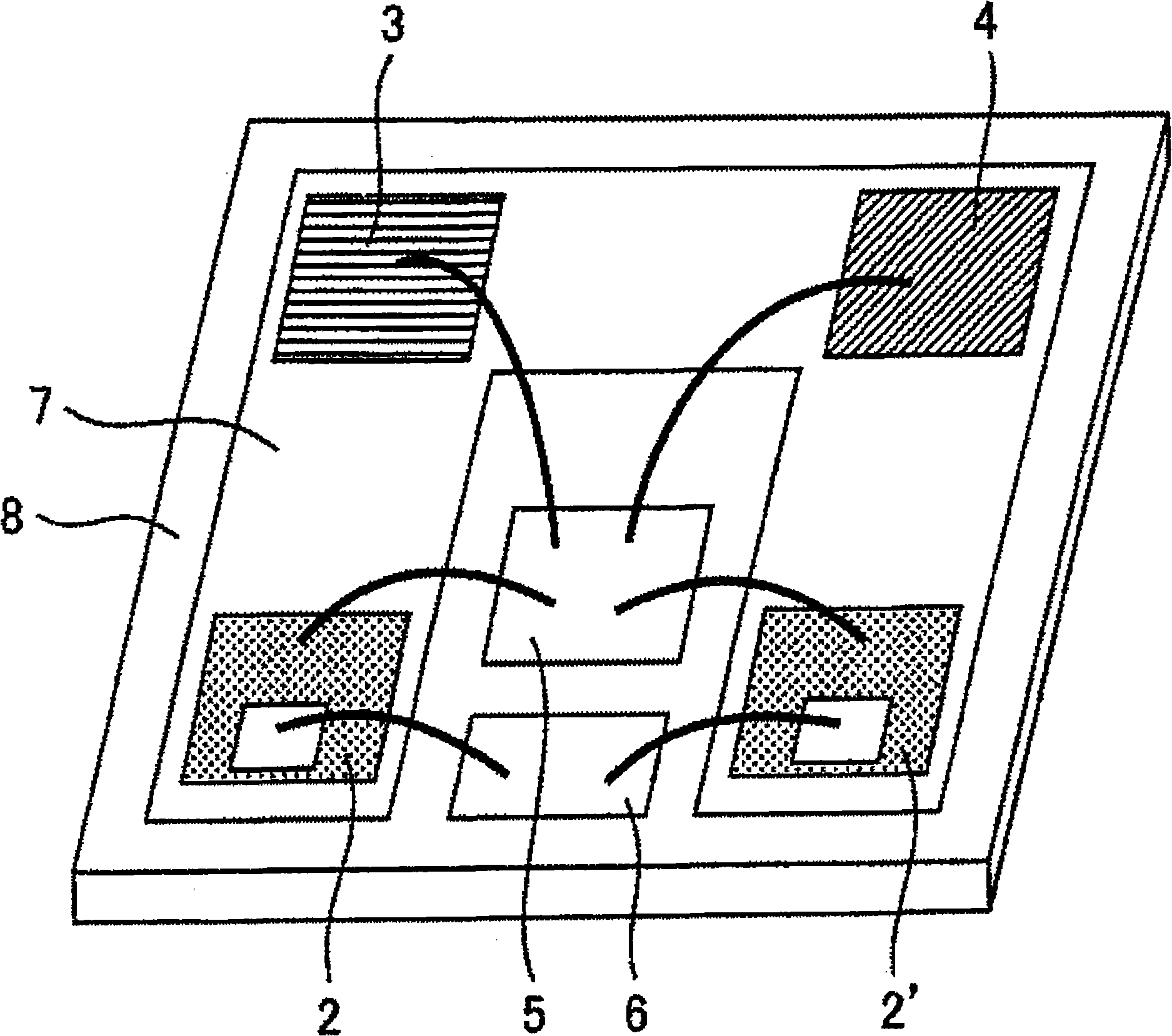
[0057] Example 1 will be described. This example is an example of a circuit device. The circuit device is characterized in that it has at least one switching element and a freewheeling diode connected in parallel thereto, and the freewheeling diode is a Schottky barrier connected in parallel with a semiconductor material having a band gap larger than silicon as a base material. diodes, and silicon PiN diodes, and these Schottky barrier diodes and silicon PiN diodes are composed of different chips. A representative example of the aforementioned semiconductor material having a larger band gap than silicon is silicon carbide (SiC). In addition, gallium nitride (GaN) may also be used as the material. The freewheeling diode is used to smooth the sudden change of the circuit based on the switching of the switching element, to maintain the characteristic voltage and to flow the current...


PUM


Abstract

The invention provides a circuit device capable of reducing noise in a current converting circuit and reducing conduction consumption of a circuit. A representative embodiment of the invention is as follows: a circuit device is at least provided with more than one switching component and free-wheel diode connected in shunt that is composed of a schottky barrier diode (SBD) with a semiconductor material greater than silicon with a gap as the parent metal, and a silicon PiN diode connected in shunt; theses SBDs and silicon PiN diodes are formed of different chips.

Description

technical field [0001] The invention relates to a circuit arrangement having at least one switching element and a freewheeling diode connected in parallel therewith. The invention is particularly suitable for power semiconductor modules in which rectification elements are installed. Background technique [0002] A semiconductor power module is used in a wide range of fields as an element constituting an inverter. In particular, power modules using Si-IGBT (Insulated Gate Bipolar Transistor: Insulated Gate Bipolar Transistor) as switching elements and Si-PiN diodes (hereinafter referred to as PND) as freewheeling diodes have high withstand voltage and low loss. Advantages, it is used in a wide range of fields such as railways and home appliances. In recent years, the importance of energy saving has been increasing, and lower losses are required for power modules. The loss of the power module is determined by the performance of the power device, but compared with the perfor...

Claims


Application Information

Patent Timeline
Patent Type & Authority Applications(China)
IPC IPC(8): H01L25/00H01L25/18H01L29/861H01L29/872H01L29/868
CPCH03K17/732H03K17/16H01L2924/30107H01L2224/48091H03K2217/0036H02M7/003H03K17/74H03K17/567H01L25/18H03K17/687H01L2924/13091H01L2924/1301H01L2924/13055H01L2924/12032H01L2924/1305H01L2924/13062H01L2924/00014H01L2924/00
Inventor 清水悠佳石川胜美长洲正浩津川大
Owner HITACHI LTD
Why Eureka
Try Eureka