
Heavy pressure slip-casting hole-sealing method for large-diameter extraction borehole

A technology of extraction drilling and high-pressure grouting, which is used in mining equipment, earth-moving drilling, gas discharge, etc., can solve the problems of reduced sealing performance, insufficient grouting fluid pressure, easy air leakage, etc., and can lengthen the sealing depth. , The effect of reducing gas pressure and enhancing sealing

Active Publication Date: 2008-10-29
HUAINAN MINING IND GRP
View PDF0 Cites 28 Cited by
  • Summary
  • Abstract
  • Description
  • Claims
  • Application Information

AI Technical Summary

Problems solved by technology

However, this grouting sealing method cannot effectively ensure that the grout in the grouting cavity is in close contact with the rock surface due to insufficient grouting fluid pressure in large-diameter drilling. With long-term high negative pressure extraction, The borehole will lose its function after several months of use, and it is difficult to achieve the expected drainage effect
Not only that, the existing sealing slurry for large-diameter drilling is cement slurry, and the cement slurry sealing is easy to shrink and agglomerate under long-term high negative pressure drainage, and the sealing performance will also be reduced. Cracks appear between rock sections and rock sections, especially in low-permeability coal seams, and the service life of drilling is greatly limited
[0006] Most of the recoverable coal seams in the Huainan mining area are high-gas and low-permeability coal seams. With the increase of mining depth, the gas content increases, and the difficulty of gas extraction becomes more and more difficult. If the existing grouting sealing method is used, on the one hand , due to the long-term drainage of boreholes, air leakage is easy, and the drainage volume decays quickly, which cannot meet the needs of mine outburst elimination;

Method used


Image

  • Heavy pressure slip-casting hole-sealing method for large-diameter extraction borehole

Examples


Embodiment Construction

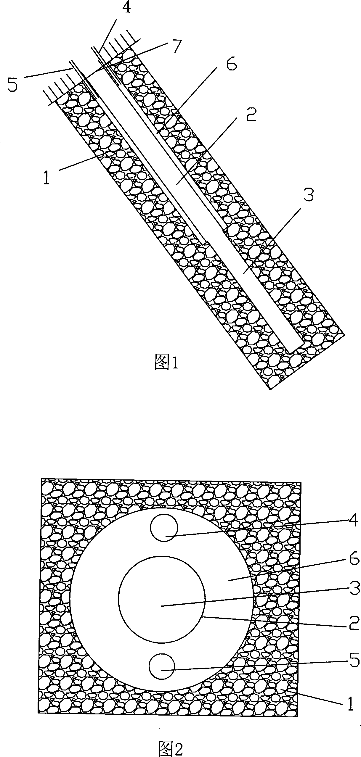
[0029] As shown in the figure, the rock face 1 is the rock layer to be drilled in the top or floor working of the coal seam.

[0030] The hole-sealing pipe 2 is a pipe arranged in the borehole to isolate the hole-sealing section from surrounding rocks.

[0031] The drainage borehole 3 is a borehole constructed for draining gas in the coal seam through the inner cavity of the sealing pipe 2 and entering the coal seam.

[0032] The grouting pipe 4 is a pipeline through which the grouting liquid is injected into the grouting chamber 6 between the rock face and the sealing pipe by a high-pressure pump.

[0033] The grout return pipe 5 is a channel for the grouting liquid to overflow after the grouting chamber is filled with grout, and it is determined whether the grouting chamber is solid by returning the grout.

[0034] The grouting cavity 6 is formed between the sealing pipe 2 and the rock face 1, and is used for injecting grouting liquid to form a seal.

[0035] The sealing e...


PUM


Abstract

The invention relates to a method for large diameter borehole extracting and high-pressure grouting hole sealing, which is characterized in that the method comprises the following steps: at the coal seam top and in the floor roadway rock surface, an across-seam hole drilling and sealing section are constructed in the coal seam; a hole sealing pipe is positioned into the hole sealing stage; a grouting cavity is reserved between the hole sealing pipe and the hole wall of a borehole; a grouting pipe and a return pipe are respectively arranged in the two positions corresponding to the grouting cavity; the output pipe of a high pressure grouting pump communicates with the grouting pipe; grouting material is infused into the grouting cavity by the high pressure grouting pump through the grouting pipe, until the grouting material overflows out of the return pipe; the hole sealing section is formed through maintenance; across-seam hole drilling is constructed in the inner cavity of the hole sealing pipe. The method has the advantages that the hole sealing effect is good, the effective gas extraction time is long, and the construction method is simple.

Description

technical field [0001] The invention relates to a method for sealing gas drainage boreholes during coal mining. Background technique [0002] In the process of coal mining, it is usually necessary to drill holes through layers in coal seams and rock formations to form gas channels so that the gas can be extracted, discharged, and further utilized. Grouting hole sealing means that in the gas drainage borehole that has been constructed, the sealing pipe is lowered, and the grouting equipment is used for grouting, so that the sealing pipe is in close contact with the inner wall of the gas drainage borehole to prevent air Enter the borehole through the cracks in the rock formation, and then connect the sealing pipe with the gas drainage equipment, and perform gas drainage through the negative pressure generated by the operation of the gas drainage equipment. [0003] Borehole drainage is an important means to eliminate gas pressure in high outburst coal seams, and the sealing p...

Claims


Application Information

Patent Timeline
Patent Type & Authority Applications(China)
IPC IPC(8): E21F7/00
Inventor 袁亮方良才郑群张士环周汝洪苏利军李勇
Owner HUAINAN MINING IND GRP
Learn More