
Vertical shaft wind motor

A wind turbine and vertical axis technology, applied in the field of machinery, can solve problems such as low wind energy utilization coefficient, poor self-starting performance, and burnt out generators, so as to improve wind energy utilization rate, reduce wind sweeping area, and increase sweeping wind area effect

Inactive Publication Date: 2010-07-07
SHENZHEN FENGFA SCI & TECH DEV
View PDF0 Cites 1 Cited by
  • Summary
  • Abstract
  • Description
  • Claims
  • Application Information

AI Technical Summary

Problems solved by technology

[0006] However, since the output power of the wind turbine is directly proportional to the cube of the speed, the wind area, and the wind energy utilization coefficient, etc., when the wind speed increases, especially in strong winds, the output power of the wind turbine rises sharply, and the speed increases rapidly, exceeding the speed of the generator. The rated power will burn out the generator, so the horizontal axis wind turbine can effectively control the power output in strong winds by changing the pitch, changing the wind angle, etc., so that the output power can be kept stable, while the vertical axis wind turbine generally It is impossible or difficult to achieve pitch change, so the ability to resist strong winds is weak. In the case of strong winds, brakes have to be used to prevent the output power from exceeding the use range of the generator, which reduces the utilization rate of wind energy;
[0007] In addition, the rotation axis of the vertical axis wind turbine is perpendicular to the wind direction, the wind energy utilization coefficient is low in small winds, and the self-starting performance is poor

Method used


Image

  • Vertical shaft wind motor
  • Vertical shaft wind motor
  • Vertical shaft wind motor

Examples


Embodiment Construction

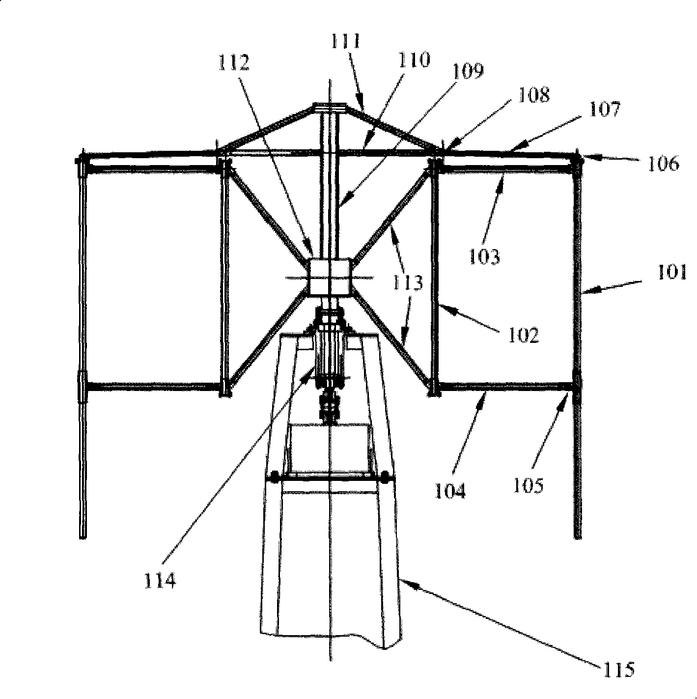
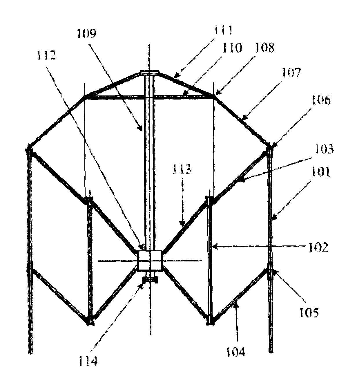
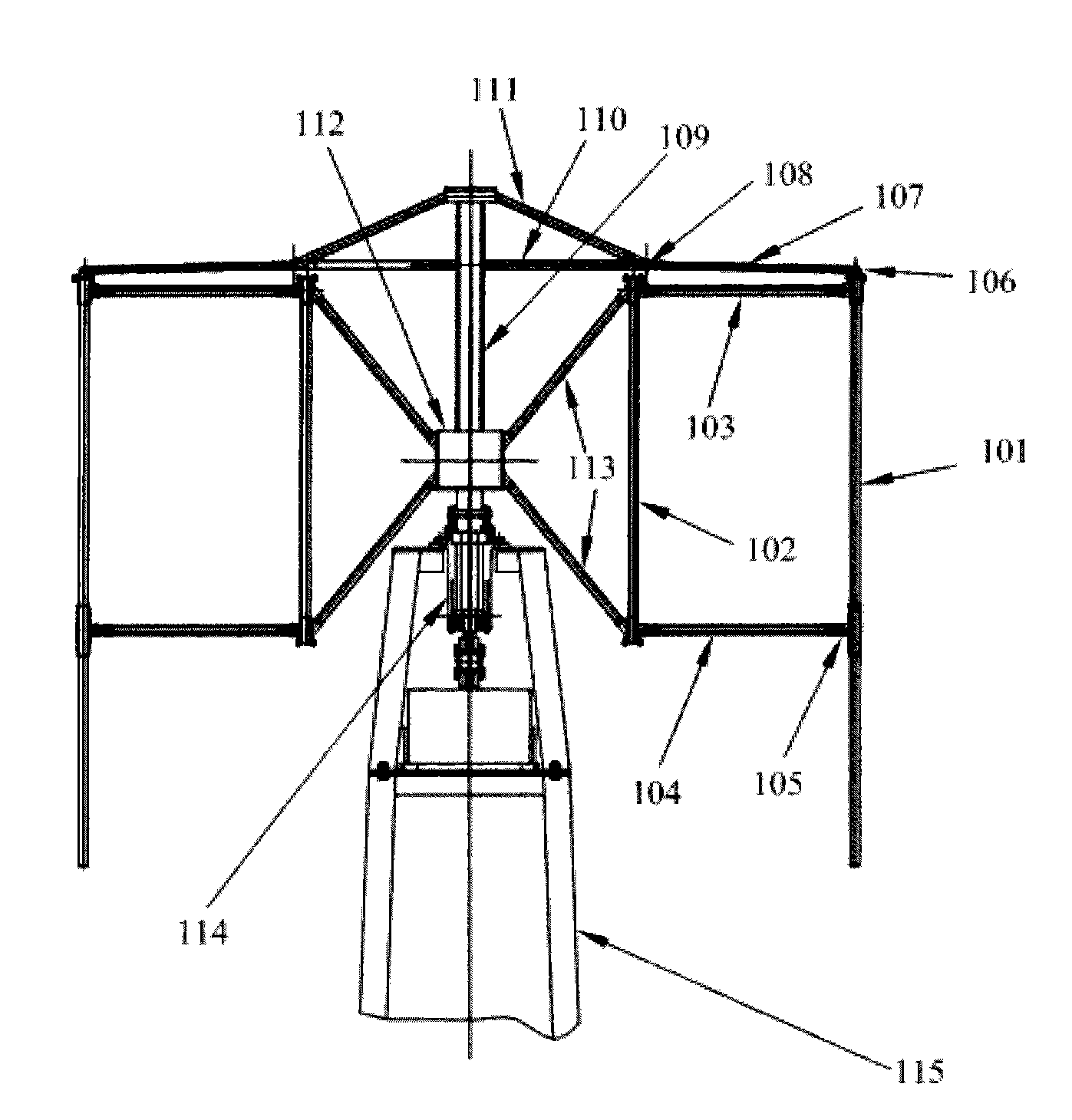
[0029] An embodiment of the present invention provides a vertical axis wind turbine, which is used for effectively utilizing wind force and reasonably controlling the power output of the wind rotor.

[0030] The wind turbine in this embodiment includes the following components:

[0031] Main blades, connectors, shafts, control systems, support shafts and towers;

[0032] The main blade is connected to the support shaft through a connector, the main blade is parallel to the support shaft, and can perform circular motion around the support shaft;

[0033] The rotating shaft and the supporting shaft are concentric shafts, the rotating shaft is sleeved outside the supporting shaft, the bottom end of the supporting shaft is connected with the control system, and can move up and down according to the control of the control system;

[0034] The connector is foldable. When the support shaft moves upward, the connector is stretched, and the main blade approaches the support shaft. Whe...


PUM


Abstract

The invention discloses a vertical axis wind turbine used for utilizing wind power effectively and controlling the power output of wind wheels reasonably. The method of the invention comprises: main blades, connectors, a rotating shaft, a control system, a supporting shaft and a tower, wherein, the main blades are connected with the rotating shaft through the connectors, are in parallel with the rotating shaft and can carry out circular motion around the rotating shaft; the rotating shaft and the supporting shaft are coaxial shafts and the rotating shaft is sheathed outside the supporting shaft; the bottom end of the supporting shaft is connected with the control system and can carry out up and down motion as being controlled by the control system; the connectors are folding type connectors which unfold and the main blades near the supporting shaft when the supporting shaft moves up, the connectors fold and the main blades apart from the supporting shaft when the supporting shaft moves down; the control system is connected with the tower and the bottom end of the rotating shaft is fixed on the tower. The wind turbine of the invention can effectively utilize the wind power and reasonably control the output of the power of the wind wheels.

Description

technical field [0001] The invention relates to the mechanical field, in particular to a vertical axis wind turbine. Background technique [0002] As a green energy in nature, wind power is currently receiving widespread attention. Wind turbines are a way to effectively utilize wind energy. [0003] There are mainly two implementations of wind turbines in the prior art, namely, a horizontal-axis three-blade wind turbine and a vertical-axis wind turbine. Wherein, the horizontal axis means that the axis line of the blade is horizontal to the ground, and the vertical axis means that the axis line of the blade is perpendicular to the ground. [0004] Horizontal axis three-blade wind turbine is the most widely used wind turbine, and its technology is becoming more and more sophisticated. However, the initial investment of horizontal axis wind turbine equipment is large, the operation and maintenance costs are high, the mechanism, system, and control equipment are complicated, an...

Claims


Application Information

Patent Timeline
Patent Type & Authority Patents(China)
IPC IPC(8): F03D3/06F03D3/00F03D11/00F03D80/00
CPCY02E10/74
Inventor 周庆余何利
Owner SHENZHEN FENGFA SCI & TECH DEV
Learn More