Centrifuges, in particular, for a lubricant oil in an internal combustion engine

A technology for centrifugal separators and internal combustion engines, which is applied in the directions of lubrication of engines, installation/connection of centrifuges and lubricant purification devices, etc., can solve the problems of heavy rotors, expensiveness, and unfavorable separation of dirt, and achieves reduction of processing costs and simplification. Effects of spare parts inventory and management

Active Publication Date: 2012-07-18
HENGST FILTER SYST (KUNSHAN) CO LTD
View PDF0 Cites 0 Cited by
  • Summary
  • Abstract
  • Description
  • Claims
  • Application Information

AI Technical Summary

Problems solved by technology

This rotor can only be made of metal due to its size, which makes the rotor relatively heavy
In addition, due to the size and weight of the rotor with the lubricating oil and deposited dirt therein, the mounting of the rotor is complex.
Due to its size and its correspondingly high mass, the rotor can only achieve relatively low rotational speeds for its drive despite heavy use of lubricating oil, which is disadvantageous for separating dirt.
It should also be pointed out as a disadvantage that many different centrifugal separators have to be manufactured and prepared for adaptation to internal combustion engines of different sizes, which makes the processing, stocking and delivery of centrifugal separators and the storage of their spare parts complex and expensive

Method used


Image

  • Centrifuges, in particular, for a lubricant oil in an internal combustion engine
  • Centrifuges, in particular, for a lubricant oil in an internal combustion engine
  • Centrifuges, in particular, for a lubricant oil in an internal combustion engine

Examples


Embodiment Construction

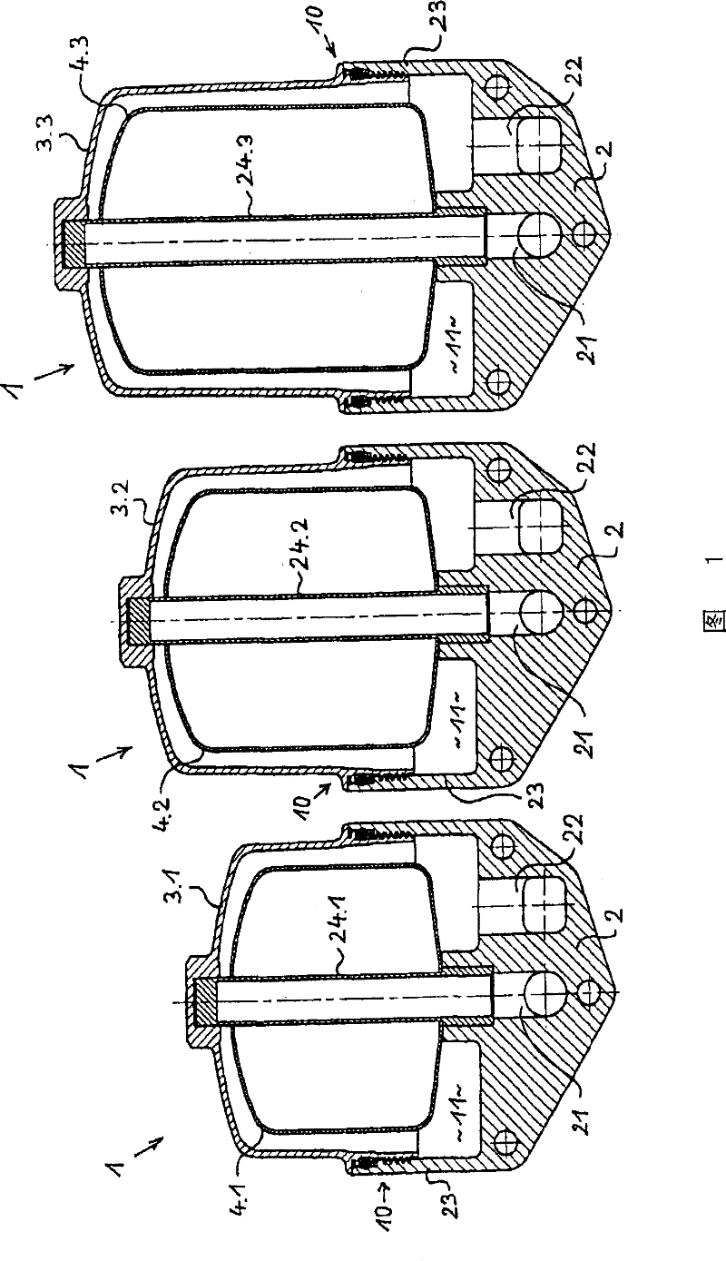
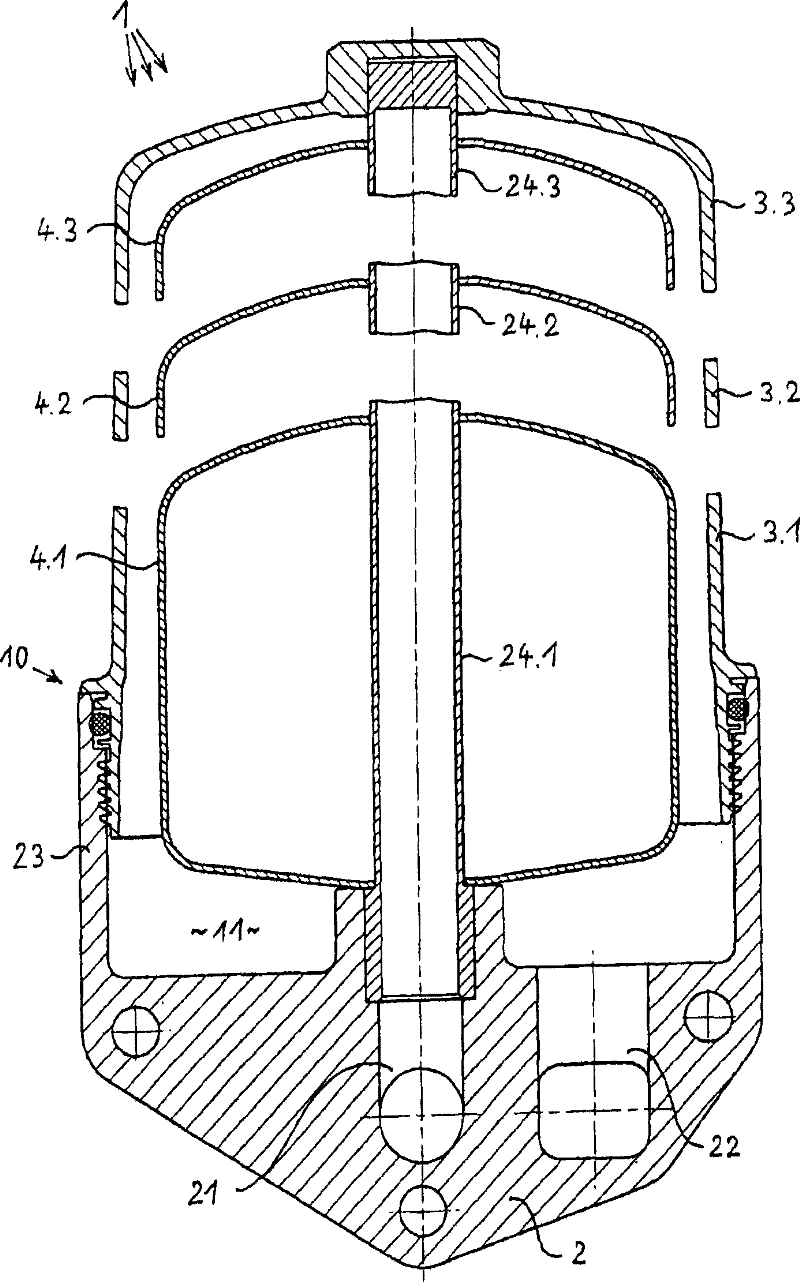
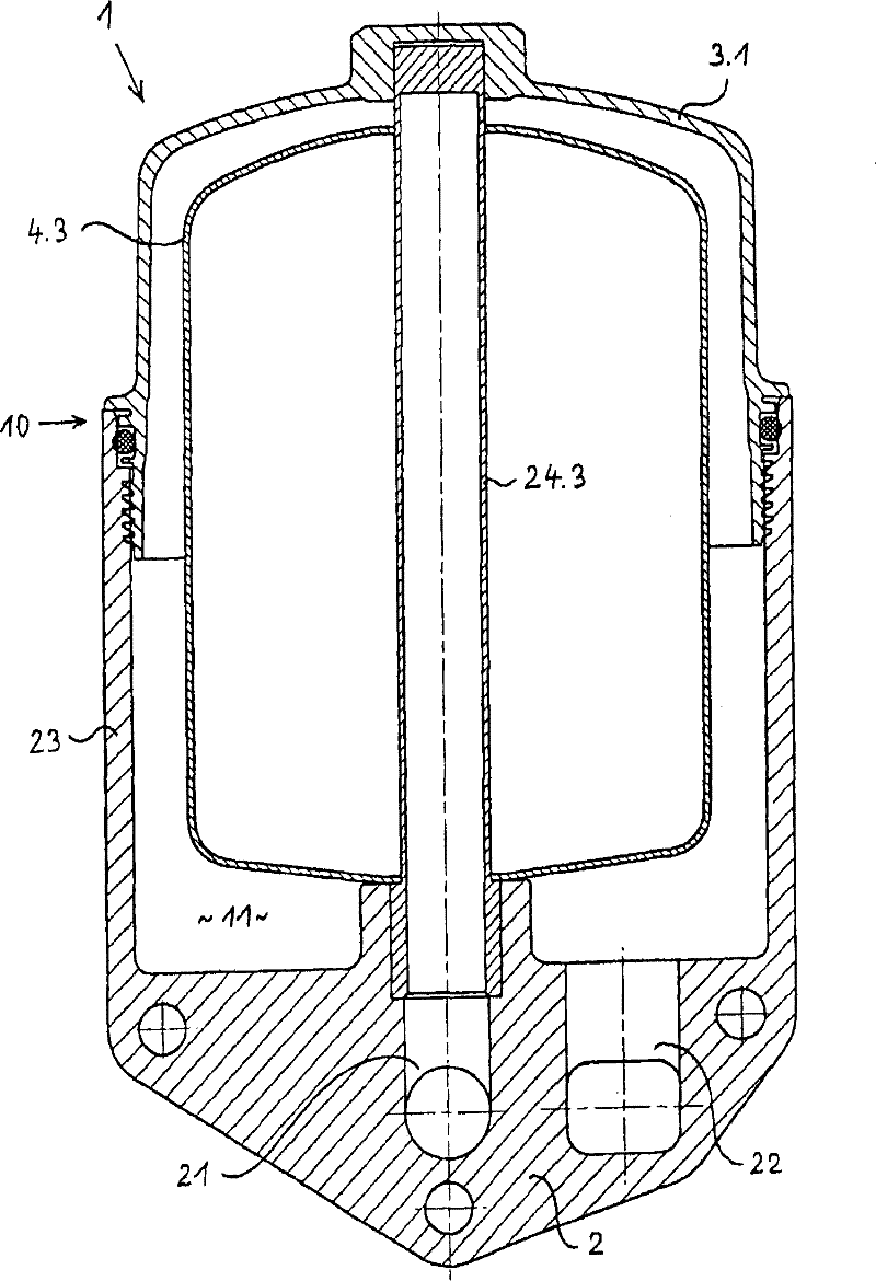
[0031] figure 1 Three different centrifugal separators 1 arranged next to each other are shown, which are characterized in that they have mutually congruent bases 2 which each form a lower housing part. Each base 2 comprises an inlet channel 21 for the liquid to be cleaned in the centrifugal separator 1 , for example the associated internal combustion engine lubricating oil, and an outlet channel 22 for the cleaned liquid from the centrifugal separator 1 . Furthermore, each base 2 includes a peripheral wall 23 which extends upwards. for in figure 1 Each of the three centrifugal separators 1 shown in FIG. 1 has a cover 3.1, 3.2, 3.3 connected to the peripheral wall 23, here detachably bolted with a sealing ring in between. The caps 3.1 to 3.3 each have a congruent connecting end for connection to the peripheral wall 23 downwards, but upwards have a mutually different height, as figure 1 as shown.

[0032] A shaft 24.1 or 24.2 or 24.3 is respectively arranged in each inner c...


PUM


Abstract

Centrifuges (1), in particular for a lubricant oil in an internal combustion engine, are provided with a housing (10) which comprises a base (2), a lid (3) forming the second part of the housing and connectable to the base (2) and a rotor (4) arrangeable in the housing (10). The inventive centrifuges (1) are characterised in that each centrifuge (1) is embodied in the form of a modular unit whichis assembled with the aid of modular system parts, wherein said modular system comprises different bases (2, 2.1 - 2.n) and / or different lids (3, 3.1 - 3.n) and / or different rotors (4, 4.1 - 4.n) which can be assembled in the form of different combinations in such a way that different centrifuges are obtained.

Description

technical field [0001] The invention relates to a centrifugal separator, in particular for lubricating oil of an internal combustion engine, having a housing and a rotor arranged inside the housing, the housing comprising a base forming a first housing part and a base forming a second housing part with the base Connector cover. Background technique [0002] Centrifugal separators of the type described above have been used for a long time and are generally known due to their widespread use, also in lubricating oils for internal combustion engines. In this use, the centrifugal separator serves to separate the fine dirt particles entrained in the lubricating oil of the internal combustion engine from the lubricating oil. In this case, the centrifugal separator is usually arranged in the partial flow of the lubricating oil circuit of the internal combustion engine, while the lubricating oil filter is usually provided with an exchangeable filter fitting in the main flow of the l...

Claims


Application Information

Patent Timeline
Patent Type & Authority Patents(China)
IPC IPC(8): B04B5/00B04B5/10B04B7/02
CPCB04B7/08B04B5/005F01M2001/1035F01M11/03F01M2001/1057B04B7/02B04B5/10B04B5/00
Inventor D·鲍曼
Owner HENGST FILTER SYST (KUNSHAN) CO LTD
Why Eureka
Try Eureka