

Method of hot metal dephosphorization treatment
A treatment method and molten iron technology, applied in the manufacture of converters, etc., can solve problems such as heavy burden
- Summary
- Abstract
- Description
- Claims
- Application Information
AI Technical Summary
Problems solved by technology
Method used
Image

Examples
Embodiment 1
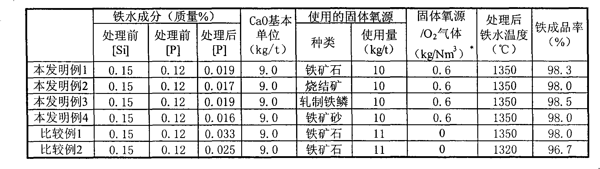
[0052] The molten iron tapped from the blast furnace was desiliconized in a blast furnace casthouse, and then transported to a converter with a capacity of 300 tons, where dephosphorization was performed a total of four times (Examples 1 to 4 of the present invention). The phosphorus concentration of the molten iron before the dephosphorization treatment was uniformly 0.12% by mass, and the phosphorus concentration of the molten iron after the dephosphorization treatment was 0.020% by mass or less, and the iron yield was set at 98% or more. The yield of iron (η) is the total mass (Wo+Ws) of the mass (W) of molten iron that is tapped after dephosphorization relative to the mass (Wo) of molten iron charged into the converter and the mass (Ws) of scrap metal Calculated by expressing (η=100W / (Wo+Ws)) in percentage.
[0053] The dephosphorization treatment is carried out using a top blowing oxygen blowing pipe, and the top blowing oxygen blowing pipe has two separate supply systems...
Embodiment 2
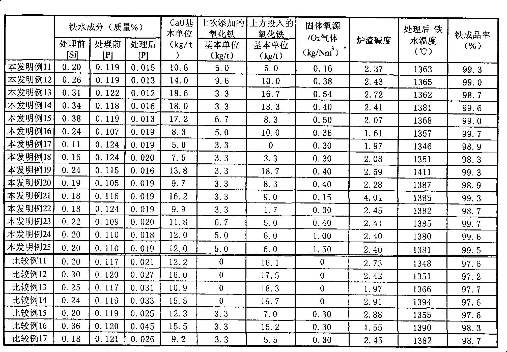
[0064] The molten iron tapped from the blast furnace was desiliconized using a blast furnace sand bed, and then transported to a converter with a capacity of 300 t, where a total of 15 dephosphorization treatments were performed (Examples 11 to 25 of the present invention). The dephosphorization treatment was carried out in the same manner as in Example 1, and the phosphorus concentration of the molten iron after the dephosphorization treatment was 0.020% by mass or less, and the iron yield was 98% or more as targets.
[0065] As iron oxide, iron ore with an average particle size of 100 μm was used. The iron oxide is supplied from the top-blown oxygen blowing pipe based on the transport gas and fed from the top of the hopper on the furnace.
[0066] As the dephosphorization refining agent, quicklime powder (average particle size less than 1 mm) supplied from the supply system of the gaseous oxygen source and lump lime (average particle size about 10 mm) fed from the upper side...
Embodiment 3
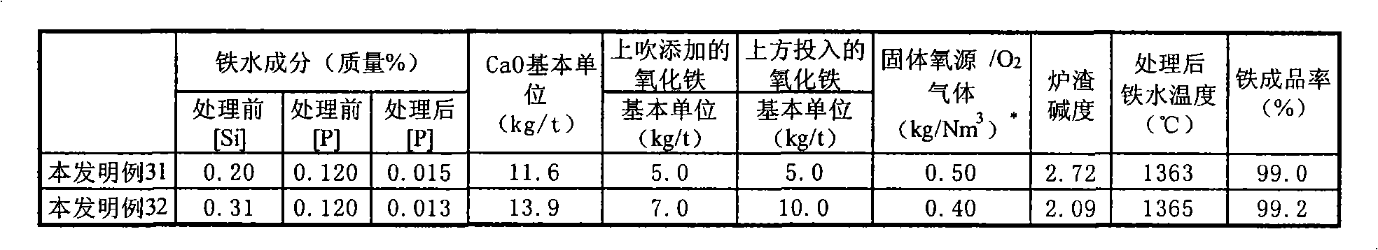
[0074] The molten iron tapped from the blast furnace was desiliconized using a blast furnace sand bed, and then transported to a converter with a capacity of 300 t, where dephosphorization treatment was performed twice in total (Examples 31 to 32 of the present invention). As the bottom blowing gas, the inner tube of the tuyere of the double tube structure at the bottom of the converter is used as the stirring gas to correspond to about 0.8Nm per 1 ton of molten iron 3 Oxygen is blown in at a flow rate of / min. Dephosphorization treatment was performed in the same manner as in Example 1, except that propane gas for cooling the tuyeres was blown in from the outer pipe. As iron oxide, rolled scale with an average particle size of 500 μm was used. The phosphorus concentration of the molten iron after the dephosphorization treatment is 0.020% by mass or less, and the iron yield is 98% or more as targets.
[0075] Table 3 shows the molten iron components and operating conditions ...
PUM
| Property | Measurement | Unit |
|---|---|---|
| particle size | aaaaa | aaaaa |
| particle diameter | aaaaa | aaaaa |
| particle size | aaaaa | aaaaa |
Abstract
Description
Claims
Application Information