
Stretching type folding probe

A stretching and probe technology, applied in the field of probes, can solve problems such as unsatisfactory, too high needle height, limited performance, etc.

Inactive Publication Date: 2008-12-03
MICROELECTRONICS TECH INC
View PDF1 Cites 8 Cited by
  • Summary
  • Abstract
  • Description
  • Claims
  • Application Information

AI Technical Summary

Problems solved by technology

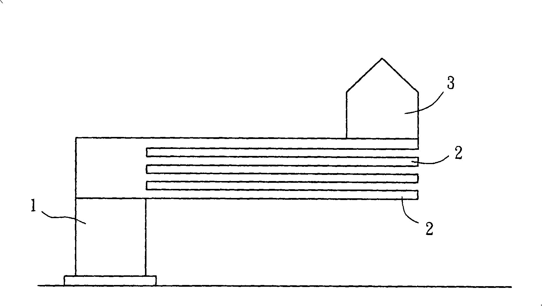
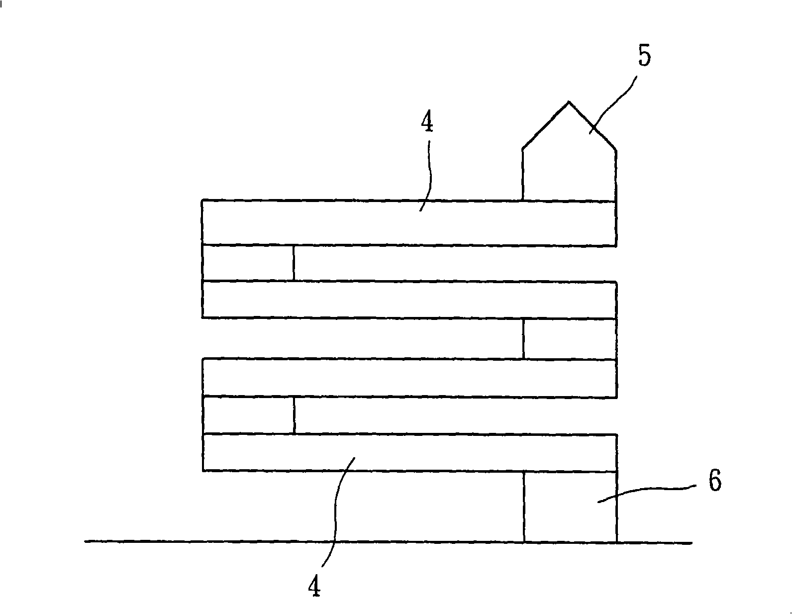
[0007] 1. The design of this type of compression elastic body is limited by the width-to-height ratio of the compression pin. When the width-to-height ratio of the compression type elastic body is too large, the traditional spring design reference limit is 5, and the compression type elastic body is prone to lateral collapse. , resulting in poor structural stability
In view of this, the needle body width of the multi-leaf compression probe must also be reduced accordingly when facing the demand for a small needle pitch. However, due to the design principle of the limited compression elastic body aspect ratio, the needle height cannot be too high That is, it is impossible to have a multi-leaf structure with too many layers, and it is necessary to reserve enough space for elastic compression deformation between the blades 4, which will further limit the number of multi-leaf structures, and thus make it impossible to achieve the purpose of reducing the maximum stress. , which limits the effectiveness of this design
[0008] 2. At the same time, this previous proposal emphasizes that the designed needle point 5 and its fixed part 6 are located on the same vertical axis. Its application is mainly designed for vertically moving test probes, but it cannot meet the small lateral displacement of some needle points. Through this, use the needle tip to draw a needle mark to scratch the oxide on the surface of the chip to be tested to improve the electrical contact requirements

Method used


Image

  • Stretching type folding probe
  • Stretching type folding probe
  • Stretching type folding probe

Examples


Embodiment Construction

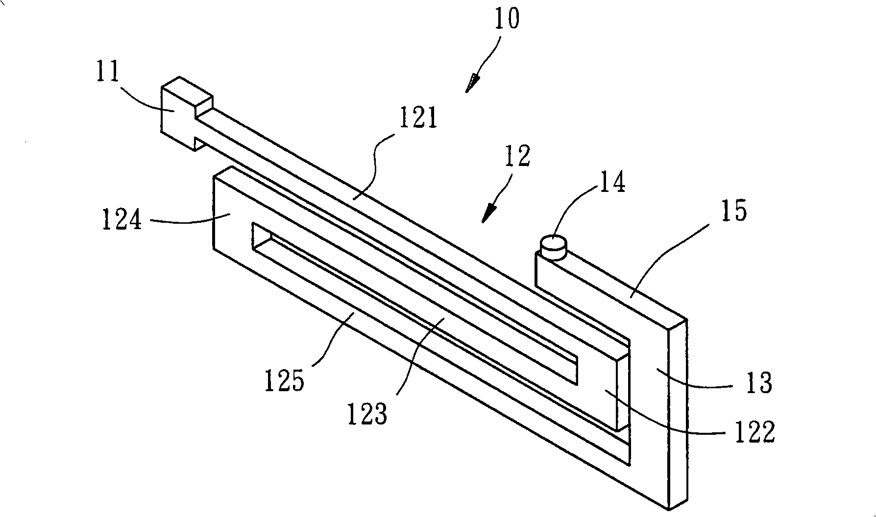
[0042] Please refer to image 3 , is a stretchable folded probe 10 provided by a preferred embodiment of the present invention, which includes a fixed part 11, a folded part 12 and a needle tip part 13 made integrally; the folded part 12 has a A first horizontal section 121 extending a predetermined distance horizontally on one side of the fixing portion 11, a first vertical section 122 extending a predetermined distance from the free end of the first horizontal section to the vertical direction, a free end from the first vertical section 122 A second horizontal segment 123 extending horizontally for a predetermined distance from the end toward the fixed portion 11, a second vertical segment 124 vertically extending a predetermined distance from the free end of the second horizontal segment 123 to the opposite direction of the fixed portion 11, and a The free end of the second vertical section 124 extends horizontally to the opposite side of the fixed part for a predetermined ...


PUM


Abstract

The invention relates to a tensile foldable probe, which comprises a fixing part, a foldable part, and a probe point part. The foldable part is provided with a plurality of horizontal sections and a plurality of vertical sections which extend from one side of the fixing part to be in continuously reversed bent connection; the probe point part which is formed by vertically extending at the predetermined distance to the fixing part through the free ends of the horizontal sections at the end of the foldable part, and the probe point part and fixing part are positioned on different axial lines; when the probe point part is contacted with an object to be tested, the foldable part is driven to be stretched, stretching elastic force is provided to allow the probe point and the object to be tested to maintain the electrical contact; the stress can be dispersed by each horizontal section, so as to increase the elastic deformation amount; meanwhile, the tensile foldable probe has better structural stability, so as to meet the requirement of high density probe distribution of micro probe point distance.

Description

technical field [0001] The present invention relates to a probe, more specifically a stretchable folded probe. Background technique [0002] In the semiconductor industry, when an integrated circuit chip is produced but not yet packaged, it must go through a test program to test the circuit function of the chip; generally, a probe card is used to set between the test machine and the chip to be tested , the probe card uses various types of probes, such as vertical, cantilever, spring probes, etc., as the contact with the chip to be tested to transmit signals between the test machine and the chip to be tested. [0003] However, as far as the vast majority of probes currently on the market are concerned, they are mainly a single cantilever beam structure, which has the advantages of simple structure, the needle tip can be approached to a smaller needle pitch, and the manufacturing cost is relatively low; but due to the strength of the material and the needle pitch In order to ...

Claims


Application Information

Patent Timeline
IPC IPC(8): G01R1/067
Inventor 陈志忠
Owner MICROELECTRONICS TECH INC
Learn More