Numerically controlled machine knife tool on-line coping device

A technology for CNC machine tools and cutting tools, which is applied in the direction of grinding machine parts, surface-polished machine tools, manufacturing tools, etc.

Inactive Publication Date: 2008-12-17
黄建明
View PDF0 Cites 14 Cited by
  • Summary
  • Abstract
  • Description
  • Claims
  • Application Information

AI Technical Summary

Problems solved by technology

[0006] 1. A blade ranges from twenty or thirty yuan to hundreds of yuan, and its utilization rate (by weight) is less than one-thousandth. Once it cannot be used, it has to be thrown away, which greatly wastes resources;
[0007] 2. After one tool tip is worn out, another tool tip has to be replaced. Such frequent replacement will damage the screw on the one hand and stop production on the other hand, which limits the further improvement of the efficiency of CNC machine tools.
Flank wear further intensifies the friction between the tool and the workpiece, increases the feed resistance, easily generates machining vibration, and affects the roughness of the workpiece surface; boundary wear further deteriorates the cutting performance of the tool (the negative rake angle of the tool is further increased), The normal cutting of the tool gradually becomes extrusion cutting
Both flank wear and boundary wear will rapidly increase cutting heat, which in turn will further aggravate flank wear and boundary wear

Method used


Image

  • Numerically controlled machine knife tool on-line coping device
  • Numerically controlled machine knife tool on-line coping device
  • Numerically controlled machine knife tool on-line coping device

Examples


Embodiment Construction

[0015] The specific implementation manners of the present invention will be described in detail below in conjunction with the accompanying drawings.

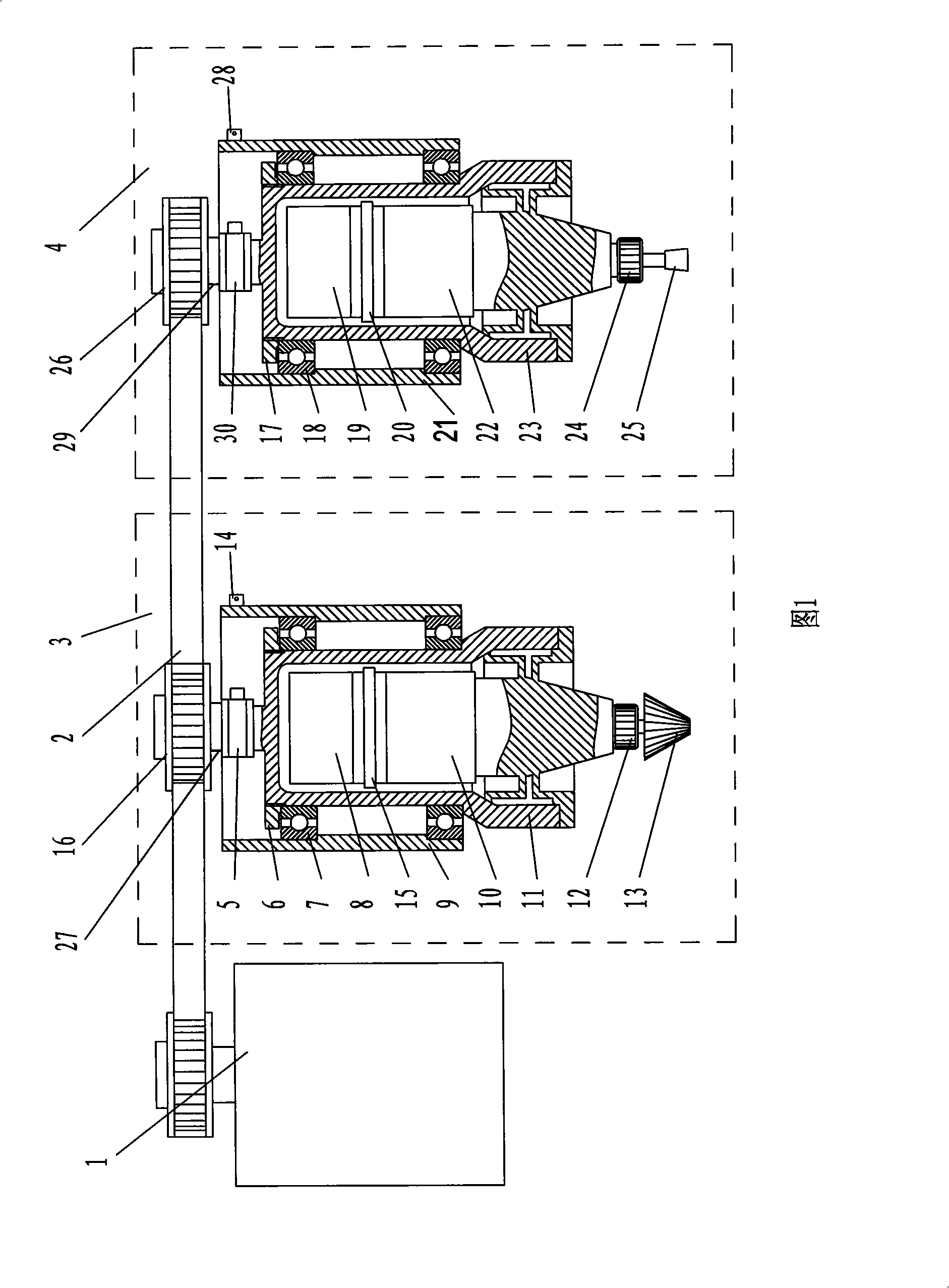
[0016] Provided by Fig. 1, the present invention includes motor, toothed belt, sharp edge rounding polishing head device 3 and ultrasonic vibration grinding head device 4, said sharp edge rounding polishing head device is, polishing head main shaft 27 one ends Polishing head toothed belt pulley 16 is housed on it, and the other end is equipped with polishing head 13 by polishing head collet 12, and polishing head horn 10 is arranged on the polishing head collet, and polishing head piezoelectric ceramic transducer 15 is contained in On the upper half shaft 8 of the polishing head, and connected together with the lower polishing head horn 10 through the thread on the upper half shaft 8, the polishing head shift lever and the polishing head piezoelectric ceramic transducer are installed in the polishing head housing 11 Inside, and ...


PUM

PropertyMeasurementUnit
diameteraaaaaaaaaa

Abstract

The invention relates to an online coping device for a cutting tool of a numerical control tool, which effectively solves the online coping problem of the cutting tool. The device is a polishing head spindle, one end of which is provided with a tooth shaped belt wheel and the other end is provided with an elastic clamp polishing head which is provided with an amplitude transformer, a transducer is arranged on a first half axis which is connected with the amplitude transformer at the lower side by a thread and which is arranged in a shell of the polishing head , the shell is arranged in an installation seat of the polishing head, the same side of a grinding head spindle and a tooth-shaped belt of the polishing head is provided with the tooth-shaped belt wheel of the grinding head, the grinding head is arranged at the lower part of the amplitude transformer of the grinding head by the elastic clamp, the upper part of the amplitude transformer is provided with a piezoelectric ceramic transducer of the grinding head, the piezoelectric ceramic transducer of the grinding head is arranged on the first half axis of the grinding head, is connected with the amplitude transformer of the grinding head at the lower side by thread on the first half axis of the grinding head and is arranged in the shell of the grinding head, the shell is arranged in the installation seat, and a motor, the tooth-shaped belt wheel of the polishing head and the tooth-shaped belt wheel of the grinding head are integrated into a whole by the tooth-shaped belt. The online coping device can be effectively used for coping of the blade of the numerical control tool and is a large innovation in the field of the numerical control tool.

Description

1. Technical field [0001] The invention relates to a processing machine, in particular to an on-line tool grinding device for a numerically controlled machine tool. 2. Background technology [0002] With the advancement of science and technology, machining machine tools are gradually developing in the direction of digitization, automation and high speed. In terms of the tools used, the extensive use of disposable tools is inevitable for the development of digitalization, automation, and high-speed machining machine tools, such as machine-clamp blades that do not need to be reground. Disposable knives have very prominent advantages: [0003] 1. Its own geometric dimension has high precision, repeat positioning and strong interchangeability; [0004] 2. It is convenient and quick to load and unload. After replacing the new blade, it can be put into use quickly without recalibrating the blade, which lays the foundation for the high efficiency of the CNC machine tool. [0005...

Claims


Application Information

Patent Timeline
Patent Type & Authority Applications(China)
IPC IPC(8): B24B3/00B24B29/00B24B41/04
Inventor 黄建明
Owner 黄建明
Why Eureka
Try Eureka