Composite power supply rail and method for producing the same

A composite power supply and manufacturing method technology, applied in the direction of power rails, chemical instruments and methods, lamination devices, etc., can solve the problems of increased difficulty in controlling the roll pass, complex production process, complex structure, etc., to achieve the promotion of current carrying and The effects of current transmission capability, simplified design structure, and simple production process

Active Publication Date: 2008-12-24
TONGJI UNIV
View PDF2 Cites 12 Cited by
  • Summary
  • Abstract
  • Description
  • Claims
  • Application Information

AI Technical Summary

Problems solved by technology

[0006] 1. It presents complex and difficult-to-manufacture characteristics in its structure
The structural design of "dimple" shape in many places makes it more difficult to control the pass shape of the roll
[0007] 2. On the extruded surface of the stainless steel profile and the extruded aluminum profile, the bimetal composite structure emphasizes the measures to break the oxide...

Method used


Image

  • Composite power supply rail and method for producing the same
  • Composite power supply rail and method for producing the same
  • Composite power supply rail and method for producing the same

Examples


Embodiment 1

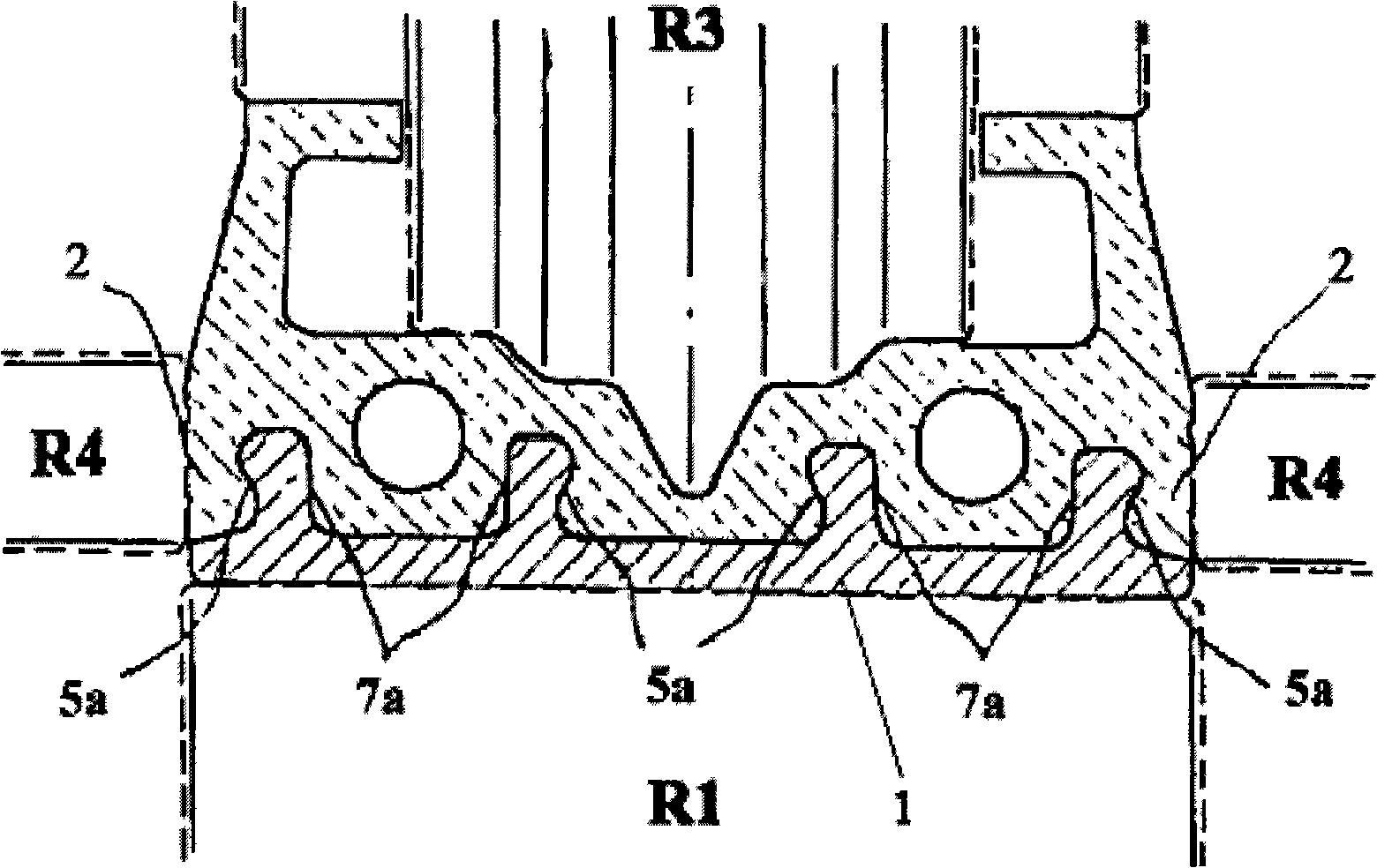
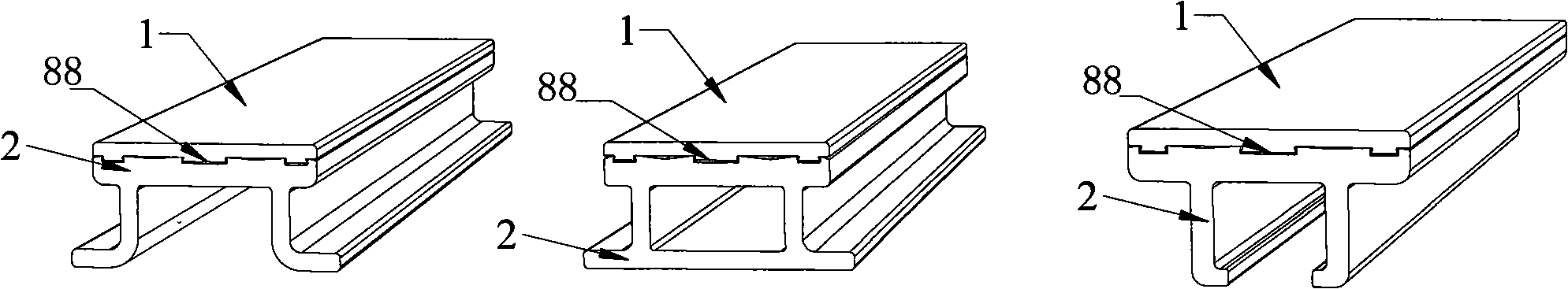
[0043] Such as Image 6 As shown, the geometry design of the current-carrying substrate 2 of the power supply rail considers the structure installed with the line track beam and the insulator, and forms a π shape with an ear 23 as a bolted body. Bolt fixing holes 22 can be drilled on the ear 23 according to the fixed position on the line track beam.

[0044] The geometry of the aluminum (alloy) extrusion profile as the base material should take into account the amount of metal deformation required for fastening the dovetail groove on the bimetal composite surface, such as Figure 7 As shown, bosses 21 and flat surfaces 24 are formed on the combined surface of the base material. as Figure 4 The shape of the boss 11 shown should also show the geometry of the metal deformation of the edge of the boss 21 to form a dovetail groove on the bimetallic composite surface of the aluminum profile. Same deal. However, when the dovetail fastening structure is formed, it depends on the ...

Embodiment 2

[0048] Such as Figure 9 As shown, the geometric shape of the composite surface of the hard wear-resistant / conductive contact body 1 and the aluminum (alloy) extruded profile matrix 2 is retained, and the geometric shape of the other side of the matrix is ​​changed to a square hole structure with ears. There are screw holes to accommodate installation needs on line track beams. The same production process as in Example 1 is used to fasten the bimetal composite surface, and the ear bolts of aluminum profiles are used to fix the power supply rail with large current and wide contact surface.

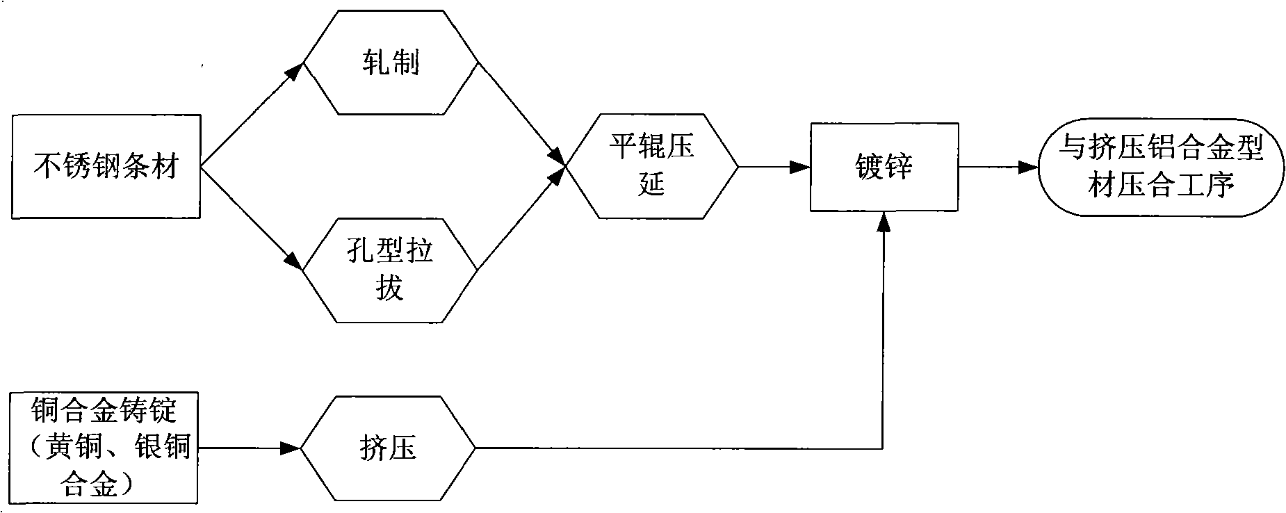
[0049] Also carry out alkali cleaning on the composite surface of the aluminum profile, partially remove the oxide layer and then galvanize to improve the adhesive strength of the composite surface, and also galvanize the contact surface of the hard wear-resistant / conductive contact metal contact body 1 . The carrier fluid of this embodiment---the geometric shape of aluminum (alloy) extrud...

Embodiment 3

[0051] Such as Figure 11 As shown, the composite surface structure of the dovetail fastening of the hard wear-resistant / conductive contact body 1 and the aluminum (alloy) extruded profile matrix 2 is retained, and the shape of the aluminum (alloy) profile matrix is ​​changed to a geometry with a C-shaped groove. Shape, use the C-shaped slot to fix the power supply rail with a pressure plate. Using the same production process as in Example 1 to fasten the bimetallic composite, and use the C-shaped groove 25 on the aluminum (alloy) profile base 2 and the pressing plate 2b to fix it on the insulator of the line track beam.

[0052] For the composite surface of aluminum (alloy) profiles, the same alkali cleaning treatment method as in Example 1 should be taken, but local alkali cleaning (only on the composite surface) is allowed to promote the bimetallic composite adhesion strength.

[0053] The geometry of the aluminum (alloy) extruded profile substrate of the present embodimen...


PUM


Abstract

The present invention discloses a complex conductor rail, and comprises a matrix and a contact body. The contact body is made of hard metal material with wear resistance and excellent conductivity; the matrix is made of metal material softer than the contact body; the rail also comprises a plating layer which is arranged between the matrix and the contact body; the plating layer is made of metal material which has excellent compatibility to the metal materials of the matrix and the contact body, and has excellent conductivity; the contact body is stitched to the matrix after being processed by the plating layer. The present invention also discloses a manufacturing method of the complex conductor rail, which comprises forming a blank of the contact body, and a blank of the matrix; one side of the blank of the contact body is a contact surface, and the other side is a compounding surface of the blank of the contact body; the compounding surface is processed by plating; one side of the blank of the matrix is the compounding surface of the matrix, which corresponds to the compounding surface of the blank of the contact body; the blank of the contact body and the blank of the matrix are stitched after being processed by plating. The metal contact surface of the complex conductor rail has the advantages of excellent conductivity, high bond strength, and simple structure. The manufacturing method has the advantages of simple technology and low costs.

Description

technical field [0001] The invention relates to a power supply rail, in particular to a composite power supply rail used in a vehicle-ground power supply system in a rail transit system, and also relates to a manufacturing method of the composite power supply rail. Background technique [0002] In order to ensure that rail transit vehicles can replenish electric energy in time in the normal operation area and parking area (station, emergency parking point), and ensure the normal operation of on-board electrical equipment, the power supply rail is the main product in the necessary vehicle-to-ground power supply facilities. Different from the catenary, some special rail transit systems require a new type of power supply rail to have its own rigidity and strength, conductive current carrying capacity, wear resistance, corrosion resistance and special structural requirements. The common power supply rail is the contact rail of bimetallic composite material. The contact resistanc...

Claims


Application Information

Patent Timeline
IPC IPC(8): B60M1/30B32B37/02
Inventor 吴祥明何大海
Owner TONGJI UNIV
Why Eureka
Try Eureka