
Crane remote wireless parallelling control system and method

A control system, remote wireless technology, applied in the direction of electrical program control, comprehensive factory control, comprehensive factory control, etc., can solve problems such as inability to lift super-long workpieces

Inactive Publication Date: 2012-07-04
TAIYUAN HEAVY IND
View PDF0 Cites 0 Cited by
  • Summary
  • Abstract
  • Description
  • Claims
  • Application Information

AI Technical Summary

Problems solved by technology

[0004] The purpose of the present invention is to solve the technical difficulties existing in the existing crane paralleling system that cannot lift super-long workpieces, and provide a remote wireless parallel control system and method for cranes that can lift super-long and super-large workpieces

Method used


Image

  • Crane remote wireless parallelling control system and method
  • Crane remote wireless parallelling control system and method
  • Crane remote wireless parallelling control system and method

Examples


Embodiment 1

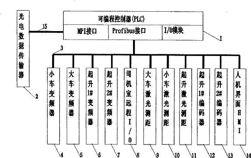
[0034] Such as figure 1 and image 3 As shown, the crane remote wireless paralleling control system in this embodiment includes a programmable logic controller (PLC) 1 including a digital input / output module and an analog signal input / output module, a human-machine interface (HMI) 14, and a trolley Inverter 4, crane inverter 5, hoisting 1# inverter 6, hoisting 2# inverter 7 and the crane control system of remote input and output module (I / O) 8 of the driver's cab, which also includes:

[0035] 1) The cart laser rangefinder 9 used to measure the running distance of the large workshop of the crane. The cart laser rangefinder 9 is composed of a cart laser rangefinder transmitter 9-1 and a cart laser reflector 9-2. The laser ranging transmitters 9-1 are respectively installed at the two ends of the girder between at least two parallel cranes, and the cart laser reflectors 9-2 are installed at the corresponding positions at the two ends of the girder;

[0036] 2) The trolley lase...

Embodiment 2

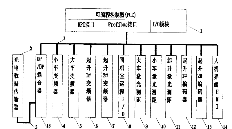
[0058] Such as figure 2 As shown, the high-speed network connection between the cranes of the parallel control system in this embodiment can also use a DP / DP coupler 16, and the DP / DP coupler 16 is connected with a programmable controller (PLC) 1 through a Profibus bus 3, and the DP The / DP coupler 16 is connected to the network with the crane to be paralleled through the wireless photoelectric data transmission module (ISD) 2 .

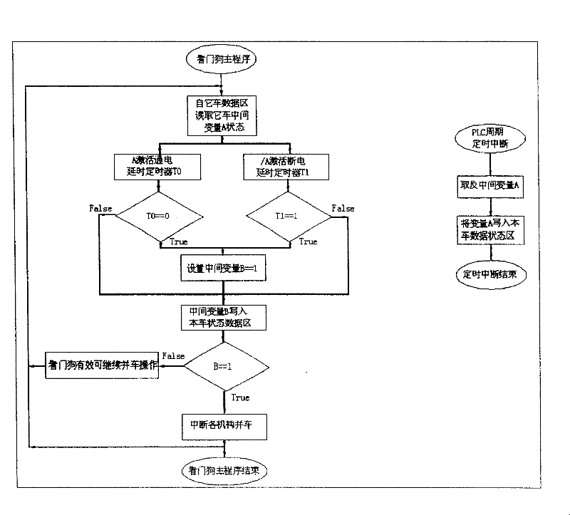
[0059] Such as Figure 4 As shown, the method for realizing the remote wireless paralleling control system of the crane comprises the following steps:

[0060] 1) Establish a data area for storing the running status of the crane on the vehicle;

[0061] 2) Establish a data area for storing the running status of other cranes that need to be paralleled;

[0062] 3) Send the data stored in the data area of ​​the vehicle to other cranes that need to be combined;

[0063] 4) Receive the data sent by other cranes that need to be paralleled and store i...


PUM


Abstract

The invention relates to a crane remote wireless parallel-operation control system and a method, belonging to the control system and the method which are applicable for remote wireless parallel-operation running when at least two crane equipment hoist ultra-long workpieces. The invention mainly solves the technical difficult point that the existing crane parallel-operation system can not hoist the ultra-long workpieces. The technical proposal of the invention aiming at solving the technical difficult point is that the crane remote wireless parallel-operation control system comprises a PLC which comprises a digital quantity input / output module and an analog signal input / output module, a human-machine interface (HMI) and a crane control system of a transducer; wherein, the crane remote wireless parallel-operation control system also comprises a large vehicle laser range finder, a small vehicle laser range finder, a rising laser range finder, an absolute value encoder and a wireless photoelectric data transmission module (ISD); and the parts are connected with the PLC by field buses.

Description

technical field [0001] The invention relates to a crane remote wireless parallel control system and method, which belongs to a control system and method suitable for remote wireless parallel operation when at least two cranes are hoisting ultra-long workpieces. Background technique [0002] The short-distance paralleling system of cranes connected by cables has been widely used in occasions where the length of the lifting workpiece is short, such as bridge cranes in hydropower stations. In the crane short-distance paralleling system, rigid connecting rods are used to connect the two cranes mechanically, and cables are used for electrical control to transmit control commands through data communication. Send the operation command to control and realize parallel lifting of the workpiece. [0003] However, for the hoisting of ultra-long workpieces, such as 100-meter steel rails for high-speed railways, due to the very large distance between the two cranes (more than 30 meters),...

Claims


Application Information

Patent Timeline
Patent Type & Authority Patents(China)
IPC IPC(8): G05B19/418B66C13/18
CPCY02P90/02
Inventor 柏俊山谭利红吴文明杜建民姚振南王吉生王首成肖利民
Owner TAIYUAN HEAVY IND
Learn More